Please Help-Another Turret controlled by PLC

Aaron_

Member
Join Date
Dec 2021
Location
Kentucky
Posts
37
I have an emco lathe I have retrofitted for a new control (mach4) and electronics. I have saved this turret for last because I knew it was going to be my biggest headache. This has proven to be true lol.

The turret is a bsv-n 160 duplomatic 8 position turret. For controlling this thing it has a 3 phase motor, absolute encoder, 24v motor brake, 24v solenoid, 24 proximity switch for the solenoid . The encoder has 3 bit signals and 1 strobe signal. PDF can be viewed here: https://macoser.com/macoser2019/wp-content/uploads/2017/11/IT6430-0908_BSV-N.pdf

each tool will see the 3 bit signals either on or off depending on the tool. Then see a strobe signal. The strobe signal would need to trigger the solenoid to lock the turret. The turret has a locating groove for the exact location of the tool. Once the solenoid drops in that groove it would signal the proximity switch to then stop the motor. This has to happen pretty fast. Which is why I went the PLC route.

I have mach4 setup for modbus to send a tool change signal to the plc on output pin Y006. That should start the Tool change program within the PLC> unless someone sees a better way to do it. Mach4 is also setup to read and write to DS1 for the tool to change to.

The PLC ladder logic is what im struggling with. I have never used one before . I have been reading and watching videos for a week or so now. I understand the basics but i cant grasp how to write this program. If someone would be willing to help me along I would be very grateful.
 
The 3 phase motor (digital phase shifter) is controlled by 2 contactors to switch it between CW and CCW going to outputs 3cw and 4ccw on the plc. The CCW rotation is only to lock the turret in place. After the solenoid switch goes high that is the tool location. The motor then turns CCW until it sees the lock proximity switch go high. Then motor rotation is stopped and the motor brake is enabled. There is a lot going on fairly quickly.
 
When I work on something I am unfamiliar with (as in a turret in this case) I create an worksheet called ToDo in the project Excel workbook and list each single item that I have to include or account for on one row.


Writing for a single task turns out easier, then add the next task. The next task may require some change to what has been written along with its code.


As you go there will be new items you think of to add and the completed items moved to the right as DONE.
 
Thanks for your suggestion. I have everything (or what I think is) listed out. on a whiteboard. The thing I'm hung up on for the most part is how do I write out the ladder logic to assign the bit signals to a tool number? Ds1 is being given a value by mach4 for the tool number 1-8.

Do I just compare DS1 = 1-8?

Then say for tool 1 which bit 1.2.3 should be 1.0.0.
DS1=1 ------- turn motor CW-------Y001 l/l-----Y002 l l--------Y003 l l---
DS1=2

Do that for every tool? Would that turn the motor until the correct bit signals were on/off then continue with the rest of the code? Or is there a better way to do this?
 
Do you just have to watch position for 8 existing tools in the turret?

Or do you have to track the possibility of a hundred different tools that could be in the turret? Or the turret can change unload and load many tools off a cassette type fixture?


If it is just 8 positions then this could simply be a counter counting up to the correct number, and if it is higher than the needed position go up to 8, reset (to 1 at the next) and go up to the needed count.


This could also be done with BSL, FIFO or a sequencer. Best to pick the method you are familiar with.


I would try to make the turret move smoothly, if a customer sees it stop at each tool they will have issues and say it is causing production delays taking the turret too long to get in position. [Not a turret, but had that happen - it caused a 1 second time difference every 5 minutes that was killing their production]
 
Yes watch the turret only 8 positions. Verified with the Encoder bit 1,2,3. Wired to the Switch PLC on X001,X002,X003.
So,

Tool 1 - 1.0.0
2 - 0.1.0
3 - 1.1.0
4 - 0.0.1
5 - 1.0.1
6 - 0.1.1
7 - 1.1.1
8 - 0.0.0

Unfortunately I am not familiar with any of those so your recommendation is what I will go with and have to figure out LOL. Luckily this is a lathe I am building for myself. I still would like it to be smooth and reliable. Although, I cannot reduce or increase the speed of the motor. Its either on or off.

If we use a counter would i still have feedback knowing the right tool was called?
 
I am currently setting the value of DS1 to 1-8 for the tool needed. Then triggering a signal on Y006 to start the PLC program. Is it possible to get the value of DS1. If its a number 1-8 Say its DS1 = 1. Could you start the motor CW and then wait until input 1 goes high and 2,3 low. then when strobe signal goes high, stop motor and enable the solenoid?
 
Does this make any sense at all? lol

If this is useable I will continue on after DS1=2 with the rest of the tools. The rest of the I/O shouldnt be that difficult. Then again i didnt think this would be either. The delay of 8Sec should be more than enough time for the turret to go from tool 1 to tool 8.

ladder.png
 
For a beginner, I personally advise against the use of Set/Reset instructions. They cause as many problems as they solve. Don't get me wrong. They have their place. But get bit experience before using them.

Rung 2: Y6 is PLC output turned on via Modbus?

Rung 3: Brakes of this type are generally electrically released, turn off the brake solenoid to engage the brake. You might need a -] [- instruction instead of -]/[- to release the brake at the signal from Y6. Rung 4 makes sense in that case. It turns on the motor when the brake is released.

But you have no logic to reset either the motor CW or the brake.

If I'm reading the manual correctly, you should also be wiring the strobe signal to a PLC input. The strobe signal tells you when the indexer is in the proper zone to fire the locking solenoid. The sequence flow chart suggests to me that you need to set up a FIFO with the positions in their proper order. When the strobe goes low you check to see if the next position in order is the target position. If it is, you fire the latch solenoid and it stops the mechanism at the next station. If the next position is not the target position the mechanism rides through it and you check again when the strobe goes low as you exit the station.

The ability to go CW or CCW lets you calculate the shortest path to the next position
 
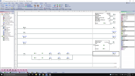
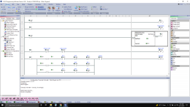
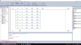
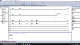
you are correct. The strobe signal is on out4 of the plc. I have it working now I will post the code. If you see somewhere i went wrong, or a way I can make it better. I just winged it and turned everything by hand taking it one step at a time until it looked as if things were functioning like they should. I then applied power to try running it under power. Luckily it worked.
 
I also stuck with CW. Just to simplify things for myself. As it takes less than 3sec to changed from 1 to 8 going CW.
 
Hopefully this helps someone else get started on down the line as i searched for 2 weeks or so looking for an answer. unfortunately i didnt find one. on the plus side i gained a little experience with PLC coding lol.

1.png 2.png 3.png
 
Let me add that x007 i have wired to an input that i am manually controlling. I am also manually setting the value for DS1 in this setup. Now that i have everything working under the PLC's control. I will implement the modbus communication and have Mach4 send the signal to start the program, Write the tool value for DS1, and have the PLC return a tool change complete signal.
 
Yes watch the turret only 8 positions. Verified with the Encoder bit 1,2,3. Wired to the Switch PLC on X001,X002,X003.
So,

Tool 1 - 1.0.0
2 - 0.1.0
3 - 1.1.0
4 - 0.0.1
5 - 1.0.1
6 - 0.1.1
7 - 1.1.1
8 - 0.0.0


Bits 2, 1 and 0 in the tool number (integer) are identical to inputs X003, X002 and X001, respectively.

So you only need 9 instructions to match X001/2/3 to DS1 (tool number) on rung 8, assuming Click PLC can address the bits in an integer, or about 5 instructions on two or three rungs if you want to a single equals instruction to know when the X001/2/3 bits match the desired tool.
 
The attached PDF sketches another approach.

  • It is a bit cleaner
  • It reads easier
    • Because it uses Start/Stop or State/Fault patterns (cf. here and here), all of the logic for each output is contained in one rung.
  • It's also clockwise-only
  • It's basically a state machine, and could be implemented with an integer state variable e.g. "if state is 0, run motor clockwise, and change to state 10 when X happens. if state is 10, ..."
  • It also uses the [4 Indexing Control] PLC-output/turret-input, as suggested in the manual (cf. flow chart on page 17 of the manual here)
  • The comments are not very good, but at least they exist.
 

Similar Topics

I've got a DH+ Network with 3 SLC 5/04's and 2 PV1000's. 1 of the SLC's is being used solely as my PC Interface - I'm doing a DF1 Pass-Thru on it...
Replies
19
Views
9,166
please help me . I have to make this ladder diagram and I can’t figure it out :(
Replies
12
Views
356
Hello, I am trying to get a Yokogawa Hart pressure Transmitter and a Rosemount Temp Transmitter to read on a 1769-IF4 module on an L33ERM...
Replies
10
Views
379
Please help me, I have solve many week but still not solve it. I found trouble of factory talk studio when I set tag by browse address of OPC...
Replies
0
Views
124
Back
Top Bottom