Please..help me about communication between S7 1200 and inverter by MODBUS RTU RS485

nguyenxuanphu

Member
Join Date
Jul 2015
Location
city
Posts
15
Hi ! Everybody !

Please..help me about communication between S7 1200 and inverter or any varispeed inverter had MODBUS support by module CM1241 MODBUS RTU RS485...!

I try to do that but not success !

Thank you very much !
 
First, do a MB-COMM_LOAD to setup port. Just once.

Use MB_MASTER to read and write. Loop.
Attached are a few PDF's from a working program for a Chinese V & T drive, Model E5-H.
 
Thank you for ur quick reply....
Please! Explain for me:
1/ Why did u use timer for REQ ?
2/How can define data lengh 1 or any number data Len ?
3/In DATA PTR pin ..did we make a DB data block contain address of inverter. ...for. send to make the inverter run or. Stop....and receive. the parameter of inverter ?

Sorry...I am new....so don't understand more. Need too. Much. learning from everyone...thank you very much.....
 
1/ Why did u use timer for REQ ?
Running 3 VFD's. Communications take time. Delay allows VFD time to read command and reply.
2/How can define data length 1 or any number data Len ?
Not sure. For my application, data length is always 1.
3/In DATA PTR pin ..did we make a DB data block contain address of inverter. ...for. send to make the inverter run or. Stop....and receive. the parameter of inverter ?
MB_ADDR is VFD address.
MODE 1 is Write to VFD. MODE 0 is Read from VFD.
I'm using DB block only for speed setting from HMI. 40006 is the memory address for the speed setting.
Start and Stop done with digital outputs and relays.
Sorry...I am new....so don't understand more. Need too. Much. learning from everyone...thank you very much.....
No need to apologize. We are happy to help.
 
Running 3 VFD's. Communications take time. Delay allows VFD time to read command and reply.

Not sure. For my application, data length is always 1.

MB_ADDR is VFD address.
MODE 1 is Write to VFD. MODE 0 is Read from VFD.
I'm using DB block only for speed setting from HMI. 40006 is the memory address for the speed setting.
Start and Stop done with digital outputs and relays.

No need to apologize. We are happy to help.

Thank you very much for quickly reply again !

So..what do you mean about start and stop done with digital output and relays ?

In winccflexible I could control read modbus from VFD ( I also use Kepserver OPC certainly ) and make tag to direct control VFD run or stop without PLC ..
So with CM1241 and CPU S7 1200 I also want to send (write) value to run VFD...

And about CM1241 RS485 module...had a female DP 9 with pỉn 3 and pin 8 for modbus signal ...so Could i use any male DP9 to connect with two line modbus (+/-) from VFD ? or must use profilebus connector to connect ?

If dont bother you..could you send a sample or your project for me to learn please ?

My email : [email protected] !

Best regards !
 
You can start and stop with Modbus commands, or use the digital inputs on the VFD.
I prefer digital inputs. If you loose communications, you won't be able to stop.

2 wire shielded cable. Last VFD on the string needs a termination resistor. If VFD doesn't have a termination resistor, you can use the Profibus connector that has resistors built in.

That's good idea ! Thank you very much !
 
You can start and stop with Modbus commands, or use the digital inputs on the VFD.
I prefer digital inputs. If you loose communications, you won't be able to stop.

2 wire shielded cable. Last VFD on the string needs a termination resistor. If VFD doesn't have a termination resistor, you can use the Profibus connector that has resistors built in.

Hi ! And now i still couldn't control my VFD by moddbus RTU S8 1200 PLC with CM1241 module .

I want to make an example to run and stop VFD by modbus...But till now I couldn't do it well !

Please ...download my file : http://www.mediafire.com/download/ibns7nhskpvgyry/modbusVFD.zip
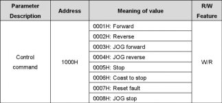
The modbus table like this :

Please..help me to make it !

Thank you very much !

address.jpg
 
You can start and stop with Modbus commands, or use the digital inputs on the VFD.
I prefer digital inputs. If you loose communications, you won't be able to stop.

2 wire shielded cable. Last VFD on the string needs a termination resistor. If VFD doesn't have a termination resistor, you can use the Profibus connector that has resistors built in.

Hi ! And now i still couldn't control my VFD by moddbus RTU S8 1200 PLC with CM1241 module .

I want to make an example to run and stop VFD by modbus...But till now I couldn't do it well !

Please ...download my file : http://www.mediafire.com/download/ibns7nhskpvgyry/modbusVFD.zip
The modbus table like this :

Please..help me to make it !

Thank you very much !
 
Do the MB_COMM_LOAD just once at startup, using a First Scan bit. Look at the example I posted earlier.
Use a 1 second pulse to pulse REQ on MB_Master for now, and monitor STATUS. The diagnostics will tell you what's failing.
Verify Modbus address. It looks like it's too big.
 
Hi ...Mr Keithkyll and everyone...
My troubles :
1/ In MB master DB at DATA ADDR ...with my VFD... which value i will write (modbus address table ) when i want to control the VFD "run forward" or "run reverse" ..."stop" maybe "1000H" or 4096 decimal...or 10001 (run foward)...4097 (run reverse) ...?
2/ When wrote the DATA ADDR ...how can make data for data block DB at DATA PTR (In MB master DB)....?
I tried to do many and many time..but till now didn't success ....please help me to pass this trouble ...
Thank you very much !
 
We must proceed step by step here:

First: Skip/delete the write block.
Just try to read a value from the VFD.

Check if the address of the CP-card is correct.
Also the speed and characther length/parity.
I recon you'll have to do a cold restart/reinitiallization when you change parameters.

If you don't get any response try to switch A and B (+/-) connectinons. In my experience, there is no standard definition of these signals.


If there's still no response, check if you get an error value in the Status parameter. This value is only valid when you get the 'Done' or 'Error' bits. So to be able to read it, you must copy (move) the Status-value to a spare word (MW or DBW) when you get the 'Error' or 'Done' bits.


When you get the reading working, you know that the settings and the line is OK. Then you can proceed with the writing.


Kalle

Thank you very much !

And now I had a trouble when pin Busy of MB master DB in true..and the Done pin was false ....so my communication still not completed..
 

Similar Topics

we have siemens pc677 touch screen running iconics program opc and others from german beverage khs machinery .. also we have siemens plc 400...
Replies
0
Views
1,803
Hello All, I am trying to upgrade the SCADA on site from version 6.0 to version 7.2. I've gone from 6.0-6.2, 6.2-7.0 and finally 7.0 to 7.2 and...
Replies
4
Views
5,441
I cant get my Allen Bradley Compactlogix 1769-L32E to communicate with my 2711-B6C5 Panelview. When i configure the system protocol on the...
Replies
1
Views
1,595
I have one CJ2H-EIP21 PLC with an ethernet hub connected with some devices. There is another CJ1 PLC with ETN21 module also with a hub connected...
Replies
5
Views
2,960
please help me . I have to make this ladder diagram and I can’t figure it out :(
Replies
12
Views
356
Back
Top Bottom