Powerflex 700 Torque Control Tuning

Laminar

Member
Join Date
Jul 2019
Location
US
Posts
34
Hello all,

I am using a PowerFlex 700 (Rev 10.001) to maintain tension in a web. We're reading lbs from load cells under one of the rolls, feeding that to the ControlLogix, coming up with a torque setpoint for the drive, then sending that over EIP as [drive]:O.TorqueSetpoint1.

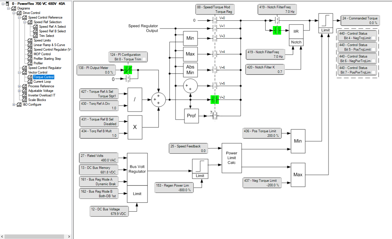
In the drive, par 88 is set to "Torque Reg."

The PF700 manual is extremely sparse on details regarding torque reg control, but I'm assuming par 527 "Kp Torque Reg" and 528 "Ki Torque Reg" are the applicable tuning parameters. The 2022 PF700 manual does not mention these parameters, but an old 2006 document does discuss torque control briefly and mentions 527 and 528.

My issue is this - at certain web speeds, the web tension varies wildly, swinging +/- ~1500lbs for a 1700lb setpoint. This happens in our middle speed range, and once we get above or below that speed, control settles out. If operation calls for running at that speed, tension swings continuously, threatening to break the web and possibly damaging our equipment.

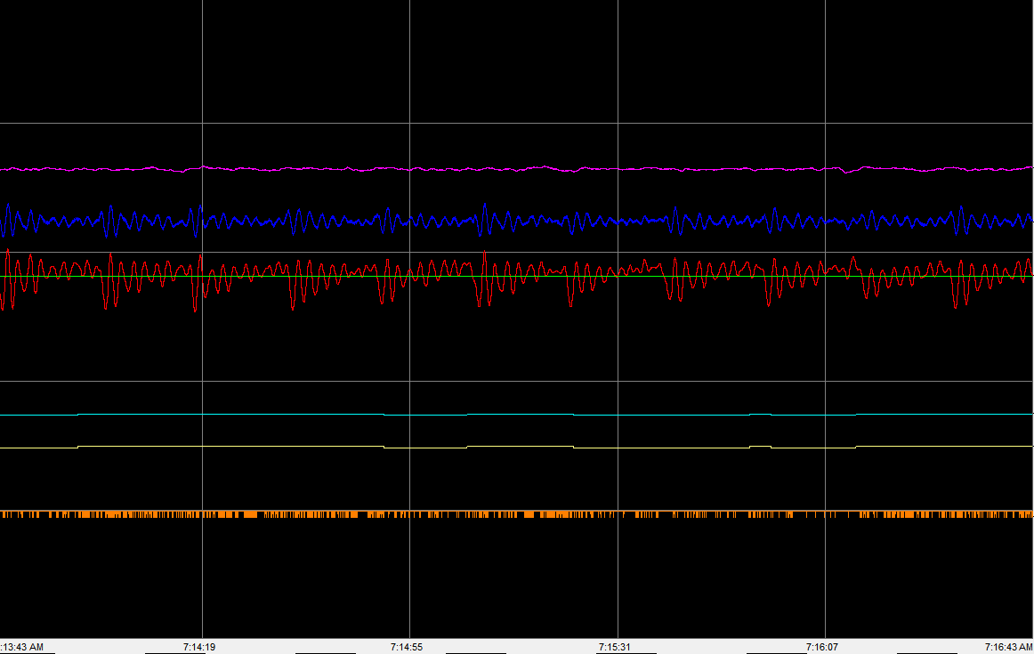
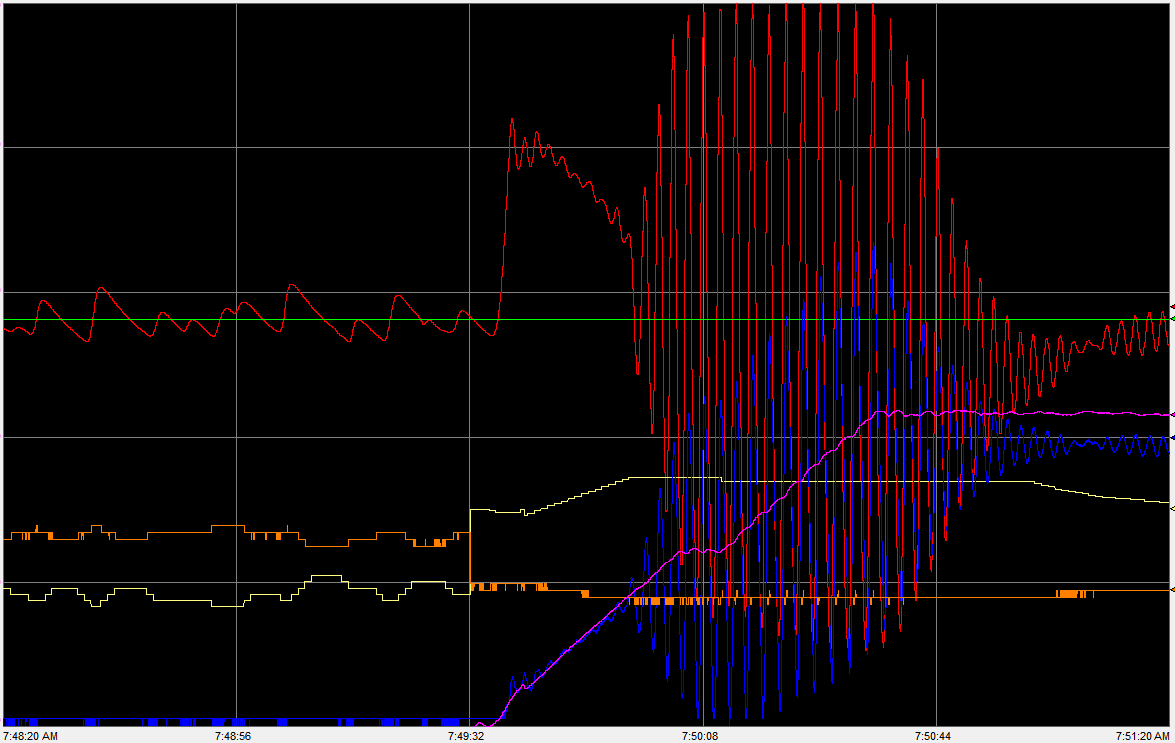
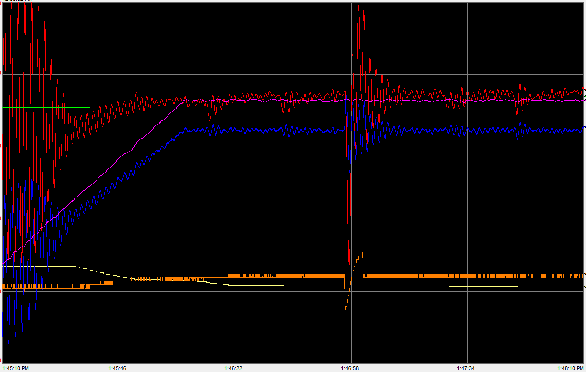
Here's a trend of the phenomenon (this is not the most severe swinging we see, but it demonstrates the behavior well):
pretension-ramp-1-702x600.png


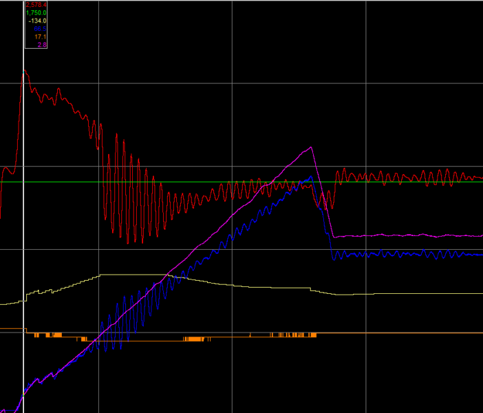
Red is the measured web tension.
Green is the desired tension setpoint.
Purple is overall web speed.
Blue is tension control motor RPM via encoder feedback.
Yellow is the O.TorqueSetpoint1 signal from PLC to drive.
Orange is the motor current feedback from the drive - each step is 0.1A.

As you can see, it starts out stable, enters a period of high instability, then at a certain speed levels out. As mentioned, if we stay in that mid speed range, the oscillations will continue indefinitely. The actual motor RPM is swinging per the blue line, but the motor output current (orange) appears to be perfectly stable in that oscillation zone.

Here's what I've tried:
- Adjusted Kp and Ki Torque Reg to absolutely no effect - not better, not worse, no effect. I can nearly zero them out and I can make them 10-100 times their original value and there is no change whatsoever in response. The parameters are currently set to the drive default parameters of Kp=32 and Ki=128.
- For fun, I adjusted the other Kp and Ki values in the drive, but they also had no effect, better or worse
- Stopped the incoming motor and ran purely off the compensator before the tension control motor - no change, the previous motor and compensator aren't inducing the swing.
- Monitored the motor after the tension zone - a small cycling effect is seen on that motor, but I assume it is in response to the swinging tension and not driving it
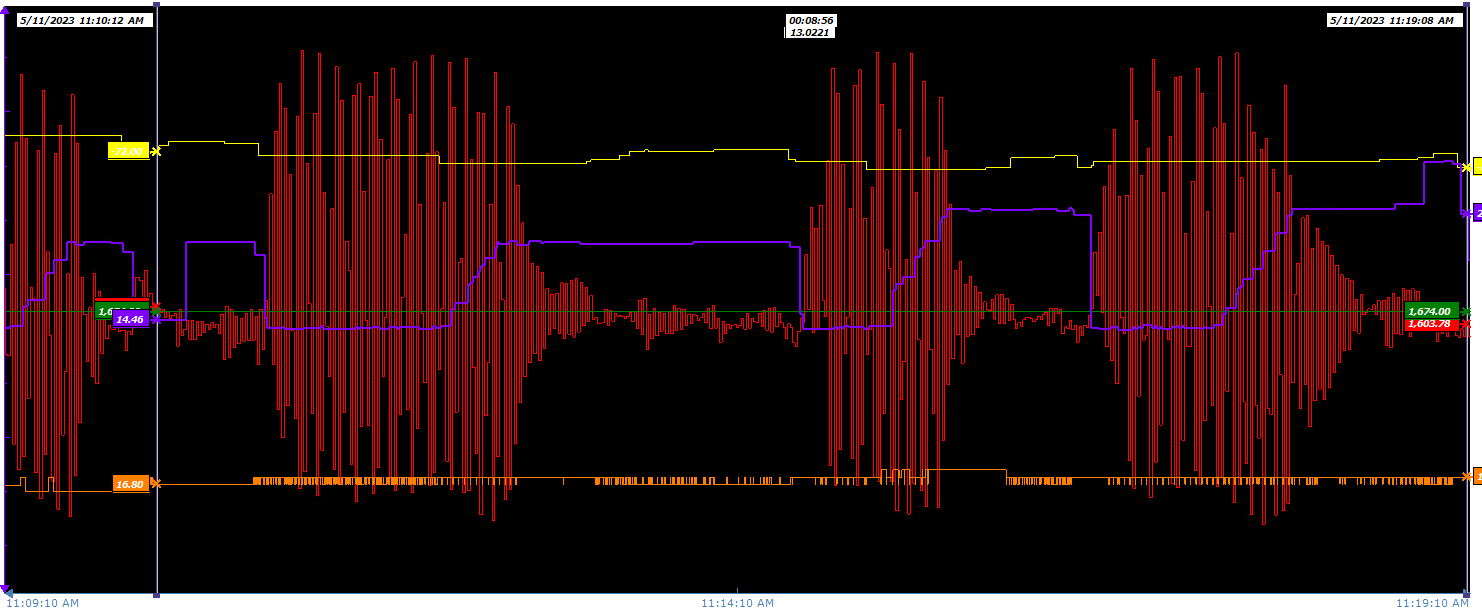
- Held the O.TorqueSetpoint1 value constant, oscillations continued
- Configured the program to detect an oscillation condition and hold the O.TorqueSetpoint1 value constant to ensure I'm not exacerbating the issue (you can see the yellow line go flat during oscillation).

I do not know when this phenomenon began, we keep 1 month of historical data and I can see it happening a month ago, but it has not always happened. I am not aware of any physical changes to the machine or the material. I can't detect any backlash in the tension control motor/gearbox. I do not know "what changed" that initiated this behavior. There have been no major intentional or unintentional modifications to the machine, instrumentation, or program.

Different materials do react differently. Some are unstable until we are over 30ypm, and some materials flatten out by 22ypm.

Maintenance wants to change out the motor encoder and has one on order, but I am not convinced that a bad encoder would act this way - I'd expect a complete failure and not a weird oscillation in one speed zone. It's also very strange to me that the tuning parameters in the drive have no effect. At the very least I would expect to be able to make it worse, but I can't even do that.

Any thoughts on next steps? I'd hate to hang my hat on the encoder being the issue and get caught with my pants down when replacing it doesn't cure the problem.
 
A couple of questions:
1. What graph time scaling?
2. Do unacceptable vibrations always start when the O.TorqueSetpoint1 signal "makes a corner" (1st vertical grid line)?
 
First of all, excellent job of gathering data. It would be nice if everyone would gather trends like this. I do agree with MaxK though.

Encoders aren't that noisy. However, they can have poor resolution and you haven't provided that information. A higher resolution encoder will help but I don't think it is the main problem.

I wonder how smoothly the web material rolls over the rollers.

It sounds like the gain changes didn't make much difference. The output to the drive and feed back do not show all the variations that the web system does. This leads me to believe it is not the control but the feed back or what ever is affecting the feed back that is causing the problem but encoders don't have that much noise unless the resolution is low.

It could be a mechanical problem.
 
A couple of questions:
1. What graph time scaling?

Major divisions are 40 seconds, total trend is about 3 minutes 2 seconds. Period of oscillation is about 2 seconds.

2. Do unacceptable vibrations always start when the O.TorqueSetpoint1 signal "makes a corner" (1st vertical grid line)?

The oscillations are triggered purely by line speed. The O.TorqueSetpoint1 signal making a corner is due to my coding freezing the setpoint in response to oscillations starting.

First of all, excellent job of gathering data. It would be nice if everyone would gather trends like this. I do agree with MaxK though.

Encoders aren't that noisy. However, they can have poor resolution and you haven't provided that information. A higher resolution encoder will help but I don't think it is the main problem.

Encoder is 1024 PPR, model Reliance RAHS35M.

I wonder how smoothly the web material rolls over the rollers.

The motor drive roll is steel and it is coupled with a coated roll via a chain. The web wraps around both rolls to provide grip to the drive roll and isolate the tension zone. Coated roll is new, bearings are new, chain tension is set properly, alignment is as good as we can get it with a pi tape.

It sounds like the gain changes didn't make much difference. The output to the drive and feed back do not show all the variations that the web system does. This leads me to believe it is not the control but the feed back or what ever is affecting the feed back that is causing the problem but encoders don't have that much noise unless the resolution is low.

This part is kind of blowing my mind - how do we swing from 100lbs of tension to 3200lbs of tension and show almost no change whatsoever in motor current? The motor current value is read directly from the drive: [DRIVE]:I.OutputCurrent. I don't know if there is some kind of damping or filtering on that value that would numb it down so much, but with that magnitude of swing in tension and motor RPM, I'd expect to see some kind of response in the current.

It could be a mechanical problem.

Definitely. Other than the things we've already checked (gearbox backlash, bearing condition, roll alignment, roll undercut, roll surface condition), what else could we look at?

Here is the system running at steady state, 40ypm. You can see there is a natural cycle to the red tension reading, like something induces an instability but it naturally dampens out. Period of that cycle is about 18 seconds.

pretension-steady-1.png


Thank you for all of the help so far - as you can see I've been exploring a lot of avenues with this one and I'm hoping it's just something I'm missing.
 
Here's another more severe oscillation. You can see it initiate as speed comes up and once we reach run speed, it dampens itself out. If we continue to run at that middle speed, it will oscillate indefinitely, the phenomenon isn't tied to a speed ramp or change.

pretension-ramp-3.png
 
The oscillations are triggered purely by line speed.

Convince me

Here is the system running at steady state, 40ypm. Period of that cycle is about 18 seconds.

Does the period vary with speed?


I know a little about math simulating. If you want we can try to simulate the system. BUT I warn you that this will be a very long and tedious process (mostly for you). At first mechanical / kinematic diagram of the process is needed
 
This time is looks like the motor does cause the oscillations at 7:49:32.
It doesn't look like there was any ramping of the torque. ( yellow ).
Before that was the system really stopped? And yet there was a small oscillation?
One more thing. Are you using the derivative gain? Motors in Torque mode need to use the derivative gain.
 
Convince me

The phenomenon repeatedly happens only in a certain speed range. Above or below, no oscillation. Stay in that speed range, it will oscillate indefinitely. Outside of that speed range, never an oscillation. Here's a longer trend (taken from Historian instead of live, I tried to make the colors match), every time we dip down into the danger speed zone the oscillations kick in, then every time we speed back up they clear up.

pretension-ramp-4.png


Does the period vary with speed?

I see the same period at 24ypm and 40ypm line speed.

I know a little about math simulating. If you want we can try to simulate the system. BUT I warn you that this will be a very long and tedious process (mostly for you). At first mechanical / kinematic diagram of the process is needed

I appreciate the offer, hopefully it doesn't come to that. 🤞🏻

This time is looks like the motor does cause the oscillations at 7:49:32.

I agree, from the trend it looks like a spike in motor rpm caused a drop in tension.

If it truly is the motor instigating the oscillations, I would sure love to be able to tune it out, but now we're back to my first post - I cannot find any worthwhile documentation on the torque control mode and nothing I change in the drive has any observable effect on the control loop.

It doesn't look like there was any ramping of the torque. ( yellow ).

This program predates my tenure, but in essence someone needed a PID loop but REALLY didn't want to set up a PID loop, so it's a series of about 20 rungs designed to proportionally change the output based on error between SP and PV (sure sound like a PID loops to me...). Additionally, the setpoint gets stepped up or down depending on machine run mode. It is clunky, but it has (mostly) worked for years.

Before that was the system really stopped? And yet there was a small oscillation?

Yes - the system should maintain tension even at 0 line YPM. In practice, the measured tension ramps down (I assume the material slowly slips across rolls, losing tension), and once the measured tension gets low enough, the tension control motor runs in reverse for just a moment, spiking the tension above setpoint. Rinse and repeat for as long as the machine is stopped with tension control active. The motor seems to step between 0RPM and -14.3 RPM during this time. There is apparently some speed or setpoint threshold in the drive that triggers it to begin movement - I am sending the O.DriveLogicRslt_Start and a constant O.TorqueSetpoint1 value the entire time, the cycling appears to be fully within the drive.

One more thing. Are you using the derivative gain? Motors in Torque mode need to use the derivative gain.

Par 459 [PI Deriv Time] is set to 0.00 Secs, the default. I don't see another derivative-related parameter applicable to torque mode?
 
Last edited:
Stumbled on this in the PF700 manual:

torque-loop.png


Would there be any value in playing around with the Notch filter (par 419, 420) or the inertia (par 450)?

Or maybe setting up PI (par 124) for torque trim?

I'm grasping at straws here.
 
Okay, for the first time ever I was able to affect the control loop:

pretension-notch-1.png


At about 1:46:57 I changed the notch filter freq (par 419) from 0.0Hz to 0.5Hz. At about 1:47:00 I changed it back to 0.0Hz. I chickened out when I saw actual effect for the first time - maybe it would have settled out. If the natural frequency of the loop is the 2 second cycle period, is 0.5Hz the right setting for the notch filter?
 
First without the ability to see the whole system it hard to give you advice
You have a nice graph but that doesn’t show it all
I see that you have an encoder installed on the motor and you are using that to measure motor speed. That also makes me think that you are using it to as speed feedback for the motor and also the drive is running in vector mode with torque limiting. If that is the case then the drive is fighting it’s self.

You can only have 1 control mode on a drive you must choose the control method.
If the drive is in vector mode it must be speed control as itwill do everything it can to have the run at the commanded speed if the current limit is to low the it will keep the motor from achieving the command speed but the error will keep growing and the motor speed will become unstable as you are seeing here.

If you want to choose speed control then vector is the way to go but the torque limit must be set to 100% and allow the drive to control speed
If you chose torque control then do not used vector control, select V over F control and set the speed reference to above the expected speed needed. Then use the torque limit to control the torque produced by the motor. If the torque required to do the work is less than the torque limit reference the motor speed will run at the speed reference but when the torque produced equal to the torque command that will determine the motor speed. The control loop should be torque feedback to the drive equals torque reference. Us the speed reference to just keep the no load speed in a safe range. The motor speed will be what it needs to maintain torque the actual motor speed could be zero if the torque reference is set to low
On winder application I like to use both but torque is final control on winders you start out at high speed and the diameter increases the motor speed needs to go down
Don’t over emphases speed when in torque control doing torque control is a bit tricky because a motor at zero speed develops zero torque.
In short check you setting carefully
 
I see that you have an encoder installed on the motor and you are using that to measure motor speed. That also makes me think that you are using it to as speed feedback for the motor and also the drive is running in vector mode with torque limiting. If that is the case then the drive is fighting it’s self.

I think I mentioned in the OP that I'm running with par 88 set to Torque Reg, not in speed control mode with torque limiting.

You can only have 1 control mode on a drive you must choose the control method.

If the drive is in vector mode it must be speed control as itwill do everything it can to have the run at the commanded speed

Which documentation are you pulling this info from?

if the current limit is to low the it will keep the motor from achieving the command speed but the error will keep growing and the motor speed will become unstable as you are seeing here.

I am not using a torque limit, I am using torque regulation instead of speed regulation. I'm interested to see your reference for all of this, as I can't find much of anything in the AB documentation.
 
Looking at the previously shared manual page, I can see that "Inertia Adaptation" and limiting are applied down stream of the notch filter. Although it does not show on this picture, I assume it is all upstream of the torque control PI.

Is there a chance that the inertia or limits are interacting with it? Are you monitoring "Motor Torque Ref 303" which I am assuming is the final reference that is fed into the torque regulator control (all inside the drive)?

PF700TRQ.PNG
 
I'm not sure if the Powerflex 700S parameters are different from the 700VC, but my parameter numbering system doesn't match that diagram. I do have a parameter 24 - Commanded Torque. Poking through the drive in the PLC I found a Diagram section that includes a live view of the torque control:

torque-control-diagram.png
 
Observing the page while running shows a rock solid Commanded Torque value, but speed feedback swings just like we see the RPM swing on the trace.

Setting the notch filter to 0.5Hz affects the oscillations - the magnitude is not reduced, the whole swing is just moved higher. Notch filter settings above 1Hz or so have no effect.
 

Similar Topics

I've got a Powerflex 700 that doesn't like to get going in the mornings. This motor will run anywhere from 30 seconds to 5 minutes before it just...
Replies
3
Views
164
Looking for some assistance. I am very familiar with Yaskawa VFDs, but not so much with AB VFDs. I am working on some hardwired AB PowerFlex 700...
Replies
2
Views
133
Can someone with Drive Executive please save me a printout of the parameters for this drive in this file. I'm in a bind and would greatly...
Replies
2
Views
362
Hello all, I was forced to replace a Powerflex 700 to a Powerflex 70 due to what is available. The digital input parameters (361-366) have a...
Replies
1
Views
486
Hello, I have an existing application that has a Powerflex 700 with a 20-COMM-E adapter controlled by a Micrologix 1100 via Ethernet. The setup...
Replies
6
Views
1,194
Back
Top Bottom