Peter Nachtwey
Member

A true story and an rant.
At least I wouldn't be guessing on whether or not increasing or decreasing gains would help.
Back in 2006 I was contacted by Rockwell to help them with a problem with a M02AS. A Rockwell customer had bought a M02AS for a flying shear. It wasn't making cuts accurately and the customer was p!$$ed and blamed Rockwell. The local Rockwell guy couldn't get it to work. I said I would go if I could bring one of our old controllers. When I got to the site and looked at the Rockwell trend I couldn't make any sense what was going on. The problem was that the Rockwell trends do not sample fast enough to see what is really happening. There was aliasing going on ( drbitboy mentioned that possibility ). To much was happening in between the samples over the back plane. I asked to have my motion controller wired up. Instead of sampling about every 10 miliseconds like the Control Logix and the M02AS, the RMC samples 1024 times a second. The problems were found within 30 minutes of wiring up the Delta Motion RMC100. The first problem was that the MDT rod was not updating synchronously with the motion controllers. This made it impossible to use the derivative gain. The customer had bought the wrong type of MDT rod. This was an easy fix. Just buy the right one. This was done quickly. The RMC plot made this problem easy to see. I still have the plots.
The second problem was MUCH more difficult to fix. The sheet metal that was being cut to length went though a pinch roller that turned an encoder. That is how positions and velocities were determined. The problem with not with the pinch roller and encoder. I could turn those by hand and the motion was very smooth. However when metal was passing though the roller the I could see the speed slow down and then jump forward. The problem was that a set of bearing on roller up stream were bad. They would cause the metal to slow down then release and jump forward. There is NO WAY a motion controller could compensate for the jerky motion. Again, the derivative gain wouldn't work. The bearing problem took months to fix. Both problems were customer problems, not problems with the Control Logix or the M02AS. The only problem with the Rockwell gear was its inability to show where the true problems lie. Again, the old 16 bit RMC100 was able to show where the problem was within 30 minutes. I still have the plots showing asynchronous feedback and the binding due to the bad bearings.
The point is that when I see a Rockwell trend I wonder would a RMC controller show? Can we see the true problem within a few minutes?
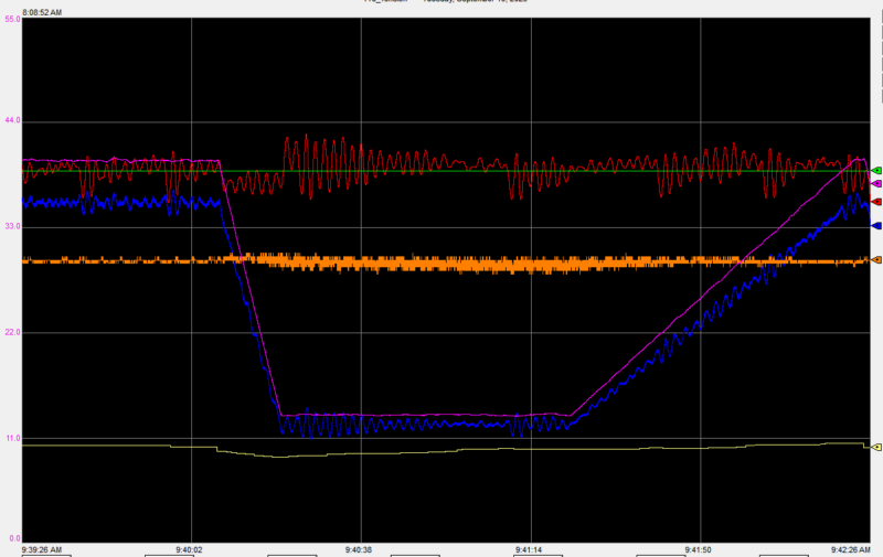
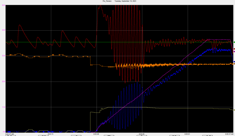
The OP's plots where not very helpful although better than nothing. I wondered if the huge oscillations were real. Can the system physically oscillate like that? The problem wasn't with the RMC100 or the M02AS.
So I can't get too excited about Rockwell trends.
BTW, the M02AS closed the loop every 250 microseconds where the RMC100 could only do it every 976 microseconds. Yet the RMC100 was able to show the problem. This was due to the packet interval between the M02AS and the Control Logix which I view as a weak link.
What really gets me is that customers blame the controllers thousands of M02AS were sold. It never occurs to the customer that their one-off machine may be the problem. However, the Rockwell trends where useless.
Also, I wrote and modified much of the code for the HYD02 and the M02AS.
I read it again. #63 doesn't look like an answer to #62.Ufff...
Let's say this: the question without an answer to which we cannot help OP is that we do not understand how his process works. In other words, we do not have a “model” of the process (#63 TF is a answer to #62. when will you learn to read?)
The videos aren't pointless. They are starting points. The OP's model should be like what I wrote above. If it isn't then why isn't it? Then you look for the why.Because we don’t have a “model” of the process, then all your videos and calculations are pointless, because... there is nothing to apply them to.
At least I wouldn't be guessing on whether or not increasing or decreasing gains would help.
It isn't useless work. That is an attitude problem. The problem is that trial an error works most of the time until it doesn't. Then look at how much time it took to figure out what is wrong.On the other hand, the OP, like any normal person, tries to avoid “useless” work and does not try to understand his process. Instead, he tries to find a “magic wand” (“magic” auto-tune, “magic” filter, “magic”...)
I said above it is a starting place which is a lot closer to the answer than guessing.Thus.
I have no doubt that you can autotune a system with a well-known model. BUT how can this help in this particular situation?
Back in 2006 I was contacted by Rockwell to help them with a problem with a M02AS. A Rockwell customer had bought a M02AS for a flying shear. It wasn't making cuts accurately and the customer was p!$$ed and blamed Rockwell. The local Rockwell guy couldn't get it to work. I said I would go if I could bring one of our old controllers. When I got to the site and looked at the Rockwell trend I couldn't make any sense what was going on. The problem was that the Rockwell trends do not sample fast enough to see what is really happening. There was aliasing going on ( drbitboy mentioned that possibility ). To much was happening in between the samples over the back plane. I asked to have my motion controller wired up. Instead of sampling about every 10 miliseconds like the Control Logix and the M02AS, the RMC samples 1024 times a second. The problems were found within 30 minutes of wiring up the Delta Motion RMC100. The first problem was that the MDT rod was not updating synchronously with the motion controllers. This made it impossible to use the derivative gain. The customer had bought the wrong type of MDT rod. This was an easy fix. Just buy the right one. This was done quickly. The RMC plot made this problem easy to see. I still have the plots.
The second problem was MUCH more difficult to fix. The sheet metal that was being cut to length went though a pinch roller that turned an encoder. That is how positions and velocities were determined. The problem with not with the pinch roller and encoder. I could turn those by hand and the motion was very smooth. However when metal was passing though the roller the I could see the speed slow down and then jump forward. The problem was that a set of bearing on roller up stream were bad. They would cause the metal to slow down then release and jump forward. There is NO WAY a motion controller could compensate for the jerky motion. Again, the derivative gain wouldn't work. The bearing problem took months to fix. Both problems were customer problems, not problems with the Control Logix or the M02AS. The only problem with the Rockwell gear was its inability to show where the true problems lie. Again, the old 16 bit RMC100 was able to show where the problem was within 30 minutes. I still have the plots showing asynchronous feedback and the binding due to the bad bearings.
The point is that when I see a Rockwell trend I wonder would a RMC controller show? Can we see the true problem within a few minutes?
The OP's plots where not very helpful although better than nothing. I wondered if the huge oscillations were real. Can the system physically oscillate like that? The problem wasn't with the RMC100 or the M02AS.
So I can't get too excited about Rockwell trends.
BTW, the M02AS closed the loop every 250 microseconds where the RMC100 could only do it every 976 microseconds. Yet the RMC100 was able to show the problem. This was due to the packet interval between the M02AS and the Control Logix which I view as a weak link.
What really gets me is that customers blame the controllers thousands of M02AS were sold. It never occurs to the customer that their one-off machine may be the problem. However, the Rockwell trends where useless.
Also, I wrote and modified much of the code for the HYD02 and the M02AS.

") . The point of this thread was to understand the process of torque control within a PowerFlex drive. I have spent countless hours at the machine and behind my screen understanding the physical process, the multitude of effects of threading, web elasticity, bearings, roller alignment, process control, why someone would waste time programming a poorly-performing PID-ish control system instead of using an actual PID block, planning shutdowns, negotiating for manpower and downtime to do inspections and testing, and more. I am very much trying to understand the entire process. I came here specifically because, as stated in the OP, Rockwell has essentially zero documentation on the function and tuning of the torque control loop and I want to understand that process.
. The point of this thread was to understand the process of torque control within a PowerFlex drive. I have spent countless hours at the machine and behind my screen understanding the physical process, the multitude of effects of threading, web elasticity, bearings, roller alignment, process control, why someone would waste time programming a poorly-performing PID-ish control system instead of using an actual PID block, planning shutdowns, negotiating for manpower and downtime to do inspections and testing, and more. I am very much trying to understand the entire process. I came here specifically because, as stated in the OP, Rockwell has essentially zero documentation on the function and tuning of the torque control loop and I want to understand that process.