Powerflex 700 Torque Control Tuning

to me, this looks like your gain is way too high on this loop. I am not familiar with the application, but numerous questions come to mind.

1) does the torque control allow autotuning?
2) is this PID control or PI control?
3) if PID, disable D (enter 0)
4) do you have access to PID parameters?
5) can you do an open-loop bump test?
6) if this happens only at high web tension, you should do all tuning near this level
7) try cutting the gain in half
 
We have all seen this driving down the road, at least those of us in the US. I suspect those in other parts of the world take care of their cars better than we do.
But when someone can explain to me how the wheel on a car moving down a highway can operate with sustained vertical oscillation WITHOUT a PID driving it into that oscillation then and only then will I believe you can stop the OP's oscillation by reducing gains ANYWHERE in the system. I fully believe you will need a gain to get you OUT of the oscillation but I am EXTREMELY dubious that it is a gain putting you into oscillation.

Keith
 
We have all seen this driving down the road,
Couldn't you be a little bit more specific? What "this"?

But when someone can explain to me how the wheel on a car moving down a highway can operate with sustained vertical oscillation WITHOUT a PID driving it into that oscillation

Such incredible technical innovations like springs and shock absorbers suspension haven't made it to the US yet?
(Strictly speaking, this is not a PID controller, but things are comparable. If your shock absorber collapses and you get into resonant bumps, I suppose you will reconsider your opinion. By the way, have you driven car with unbalanced wheels?)

then and only then will I believe

If this is the king's will,
the despicable worms
cannot but obey


you can stop the OP's oscillation by reducing gains ANYWHERE in the system. I fully believe you will need a gain to get you OUT of the oscillation but I am EXTREMELY dubious that it is a gain putting you into oscillation.

Please feel free to calculate closed loop step response
Plant TF
Wp(s) = 1/ ( (10*s)^2 + 2 * 0.2 * 10 * s + 1)
PI TF1
Wc(s) = 0.1 *(1 + 10 / s)
PI TF2
Wc(s) = 1 *(1 + 10 / s)


And I also think that it would be more useful for everyone if, before writing something in a topic, this topic would be read.

This post, as it seems to me, is not related to the OP issue.
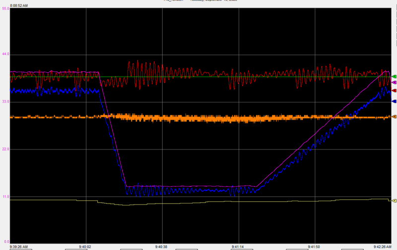
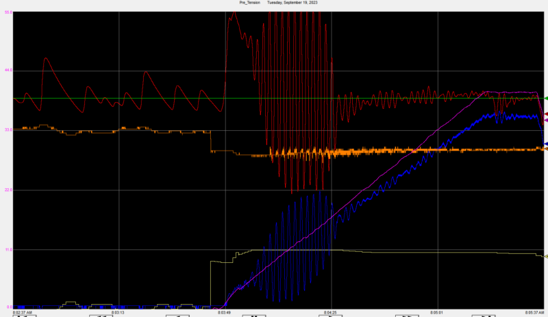
In linear (described by LDE) systems, oscillations with constant amplitude are impossible (on the OP curves amplitude is constant). Thus, I assume that there is an element with oscillation restrictions in the system (for example, a roller with a destroyed damping system, as a result of which it oscillates between mechanical stops - not yet destroyed structural elements). It would be more correct to repair the faulty element (such faults leave "traces": noise, vibration, shock, mechanical marks, etc.), but the mechanical staff hopes that the control system staff will get a magic wand and fix everything.
Let's return to the issue.
Because the system oscillates with a fairly clear self-oscillation frequency, then I believe that by changing the PID controller setting, it is possible to shift the frequency of the system relative to the frequency of self-oscillation of the faulty element. Or, by introducing a deadband into the PID controller, make the PID controller insensitive to idle self-oscillations.


BUT it may turn out that all my guesses are not worth a penny.
 
@Aliyaaii do you have a issue similar to @Laminar's?
Has anything in this thread been helpful? (useless, stupid)?
If so, could you please describe your issue and which part of this thread was confirmed/not confirmed? (any information that would help to understand the correctness / fallacy of my assumptions)
 
Hey, MaxK. That user is posting for the purpose of getting spam links online in a highly rated site. Please continue your excellent posts. Much of it is above what I do, but it's very informative and educational. Thank you for sharing your knowledge.
 
Okay, a long-overdue update. We finally got a chance to inspect the rolls in the tension zone. We found all rolls rotating freely. One was out of grease, and we found a couple of sprockets off-center and corrected those, but no smoking guns. We were able to relieve tension from over the drive rolls and run a rotational autotune. I also climbed up and got the actual motor data, and found the drive was configured for a 30hp motor (actual 25hp), 36.6 FLA (actual 34), and 1770 NP RPM (actual 1780). I corrected those values and ran the autotune, noting that we left the motor coupled up to the gearbox and drive roll. Results:

Parameter "62 - [IR Voltage Drop]" value has been changed from "7.3" to "10.8" VAC.

Parameter "63 - [Flux Current Ref]" value has been changed from "10.98" to "16.52" Amps.

Parameter "64 - [IXo Voltage Drop]" value has been changed from "98.6" to "96.8" VAC.

This morning I got a call from the operator asking what I did, because it's fixed. I've been monitoring all day, and it still gets into oscillations around the 13ypm range, but not every time, and the window of oscillation is much reduced. They can run at 24ypm without issue.

13ypm no cycling:
pret-sept-2023-2-800x505.png


13ypm cycling:
pret-sept-2023-1-e1695138464256-800x463.png


The main pattern I see right now is that when they start up from stopped and go to/through 13ypm, it cycles. But when dropping down to 13ypm from higher speeds, it doesn't cycle.

The other difference I'm noticing is that the amp signal is much more active. Where before it was mostly a straight line with some occasional changes, now it's a very fuzzy line, appearing to show more active regulation.

This discussion has been infinitely valuable to me so far, and I am interesting in hearing all of your thoughts.
 
Last edited:
I would try a notch filter at the speed where the system tends to oscillate.

I toyed with the notch filter in the drive back on page 1 - I saw an impact (but no improvement) around 0.5Hz, and no impact over 1Hz. Knowing YPM of the line at trouble speeds and diameter of the rolls, how would I calculate the frequency of the ideal notch filter? My drive roll is going about 18rpm at trouble speed or 0.310Hz.
 
If there is no smoking guns lets start from beginning

How is speed controlled? What device? What algorithm?
How is tension controlled? Is the drive braking the web or what?


Oddities
1. Red curve is the measured web tension. Blue is tension control motor RPM via encoder feedback, i.e. web speed. If I'm not a complete idiot, then the speed and tension measured at one point should be in antiphase. But the red and blue curves are practically in the same phase.

2. On all charts the vibration frequency is 18 peaks per 36 seconds (regardless of web speed). BUT on #47, #51, #53 charts I counted 26-28 peaks per 36 seconds.

Adding a filter to the closed loop (increasing the order of the system), given the fact that we cannot analyze the “model” (transfer function, Bode plot, etc.) of the closed loop (we have no data), seems to me a dubious decision.

I suggested adding a dead band to see how the system reacts - perhaps it would be possible to clap eyes on smoking guns.
 
I toyed with the notch filter in the drive back on page 1 - I saw an impact (but no improvement) around 0.5Hz, and no impact over 1Hz. Knowing YPM of the line at trouble speeds and diameter of the rolls, how would I calculate the frequency of the ideal notch filter? My drive roll is going about 18rpm at trouble speed or 0.310Hz.
I would start with the frequency of the oscillations assuming the oscillations aren't some sort of sampling artifact.
 
Are my questions too silly or too difficult? Or have you found a solution?
Your problem is quite interesting, and I would like to understand its solution
 
Are my questions too silly or too difficult? Or have you found a solution?
Your problem is quite interesting, and I would like to understand its solution
The problem is simple if there is accurate feedback and recording of the motion parameters.

Yes, there can be auto tuning in torque mode but it requires a different model than normal velocity mode. The model is very similar to that of GIT's ball and beam project.
You can tell this motor is in torque mode because the control output is proportional to the required acceleration instead of he desired velocity. The basic model is
G(s)=K/(s^2+f*s) where K is the gain in acceleration units per % control output and f is the damping or friction. It has units of torque / velocity. Notice that the f or friction term is required otherwise the virtual model would spin forever. Like GIT's ball and beam project, a derivative term is required to provide more damping. In fact tuning this motor manually is not intuitive because the derivative gain MUST BE SET first or the motor will simply oscillate back and forth because of the lack of damping. Again, this is similar to GIT's ball and beam where the ball will roll with little damping.

I was testing the picture in picture feature of the old screen recording software.
I was not testing the tuning or motion software.

I have used our autotuning to tune 250 HP motor that are moving rotary shears.
https://deltamotion.com/peter/Videos/AutoTuneTest2.mp4

So YES, a Delta Motion RMC could control GIT's ball and beam easily with the proper feedback and mechanical design. Tuning would be quick instead of taking many days with no good results.
 
The problem is simple


I'm glad that I gave you the opportunity to promote yourself once again

And I'm glad that everything is clear to you

But I’m so stupid that I don’t understand how the system described by Laplace/LDE can oscillate with a limited/constant amplitude, and most importantly, how periodic sharp bursts of oscillations can occur.

How does the system oscillate at a constant frequency of 0.5 Hz, regardless of the velocity, acceleration... whatever, but on several charts the oscillation frequency is approximately 28/36 without any known to us changes in the system?

How can one obtain the 2nd derivative for acceleration if the system is controlled by speed, not position (as in the GIT system)?

How can one advise a person who, apparently, does not understand the control theory, to add a filter to a closed loop, i.e. increase the order of the system, or in other words add a phase shift -pi/2 to the closed loop (without any closeloop model analysis!!!)

I can't even imagine how this system works in reality. So I'll try to satisfy my curiosity.
What about you... Well, I don’t know... popcorn?
 
The question that was asked was if torque systems can be auto tuned. The short answer is yes. However, I did qualify my answer by sawing the mechanical design and sampling needs to be done right. I have participated in this thread much because I have doubts about both.

How does the system oscillate at a constant frequency of 0.5 Hz, regardless of the velocity, acceleration... whatever, but on several charts the oscillation frequency is approximately 28/36 without any known to us changes in the system?
What if the oscillations are due to the system having a natural frequency because there is some compliant part of the system we haven't been told about.

How can one obtain the 2nd derivative for acceleration if the system is controlled by speed, not position (as in the GIT system)?
Git system accelerates the ball due to the tilt angle. The system in my video has a dumb amplifier that converts the input voltage to a current that produces torque.
Here is an example in Mathcad.
https://deltamotion.com/peter/Mathcad/Mathcad - Sysid T1P2 ODE-Forum.pdf
I make an open loop move and record the actual position as a function of the control output. The actual position is column 2 and the control output is column 5. The mathemagic his hidden but at the top of page 2/5 you can see that my estimated position very closely matches the actual position, so my model is good. At the bottom of the page 2/5 I plot the actual velocity generated by the difference between two position and divided by the time. Look at how noisy it is? It isn't usable. Do you really think the velocity really changes like that? It would cause the differentiator to go nuts. But look at the estimated velocity it is very clean and is a much better estimate of the velocity and his estimated velocity can be used by the derivative gain. Now look at page 3/5 where I plot the acceleration as a function of the control output. Even the acceleration is clean and accurate.

The system is controlled by current/torque. This is integrated to become velocity which is integrated again to be position.

A question I have had is are all those oscillations in the OP's graphs real or just some sampling artifacts.


How can one advise a person who, apparently, does not understand the control theory, to add a filter to a closed loop, i.e. increase the order of the system, or in other words add a phase shift -pi/2 to the closed loop (without any closeloop model analysis!!!)
I showed the auto tuning process. It takes less than 2 minutes. It generates an open loop model with a transfer function like the one I showed in the post above. If I have an open loop transfer function, it is easy, for me to place the closed loop poles and calculate the velocity and acceleration feed forward as shown in the video. Look up Akermann's method for placing closed loop poles. I use a symbolic method because it is more flexible.

Simply put, you have some misconceptions. The transfer function in #63 are wrong and this is where you start. This must be right. Also, can you write the transfer function as a differential equation? Actually, you need 3 differential equations.

How can one advise a person who, apparently, does not understand the control theory, to add a filter to a closed loop, i.e. increase the order of the system, or in other words add a phase shift -pi/2 to the closed loop (without any closeloop model analysis!!!)
Adding a notch filter doesn't need to increase the order of the system but it does in the OP's case because the notch filter must be added separately from the PID.

I can't even imagine how this system works in reality. So I'll try to satisfy my curiosity.
What about you... Well, I don’t know... popcorn?
It is hard to tell what is going on with the OP's system. The OP labeled the pens or lines on the trends well, but we don't know about the sample time or intervals. I my case I can sample the motion every 250 milliseconds i f required and I KNOW it is deterministic, so the data is good. I don't have much faith in Rockwell's trends for things as fast a motion control.

Yes, popcorn and beer when I come here.
I am retired now. What I have shown was done years ago.
Now it is time to kill some zergs.
 
Ufff...

Let's say this: the question without an answer to which we cannot help OP is that we do not understand how his process works. In other words, we do not have a “model” of the process (#63 TF is a answer to #62. when will you learn to read?)

Because we don’t have a “model” of the process, then all your videos and calculations are pointless, because... there is nothing to apply them to.

On the other hand, the OP, like any normal person, tries to avoid “useless” work and does not try to understand his process. Instead, he tries to find a “magic wand” (“magic” auto-tune, “magic” filter, “magic”...)

Thus.
I have no doubt that you can autotune a system with a well-known model. BUT how can this help in this particular situation?
 

Similar Topics

I've got a Powerflex 700 that doesn't like to get going in the mornings. This motor will run anywhere from 30 seconds to 5 minutes before it just...
Replies
3
Views
164
Looking for some assistance. I am very familiar with Yaskawa VFDs, but not so much with AB VFDs. I am working on some hardwired AB PowerFlex 700...
Replies
2
Views
133
Can someone with Drive Executive please save me a printout of the parameters for this drive in this file. I'm in a bind and would greatly...
Replies
2
Views
362
Hello all, I was forced to replace a Powerflex 700 to a Powerflex 70 due to what is available. The digital input parameters (361-366) have a...
Replies
1
Views
486
Hello, I have an existing application that has a Powerflex 700 with a 20-COMM-E adapter controlled by a Micrologix 1100 via Ethernet. The setup...
Replies
6
Views
1,194
Back
Top Bottom