Proportional two analog outputs

yes, I figured it out. i needed some time for that click in my head.

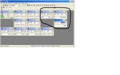
in plc sim I cant get the same values as entered in lad.
Is it always like this? In practice I suppose that has something with calibration of sensors or?

thanks guys, you are fantastic.
 
Using the ENO output from FC106 as a means of switching your analogue output voltage is unconventional (and may be be considered confusing). I'd go back to comparators.
 
why cant I in PIW456 on the slider put the temperature I set up in limits and on the MW145 number from 0 to 100 (percent)?

Sorry I bother you this much, I`m a starter. tnx

TEST.jpg
 
The purpose of FC106 is to take an engineering units value and scale it for a siemens S7-300 analogue output. Typically for analogue outputs, 0-27648 corresponds to 0 to +10v

The analogue output is addressed as PQWxx and would normally be used as the OUT value for FC106
 
Last edited:
thanks for information. this is my first project and I finished it so fast I didnt catch some basic things.

What can you recommend me from written material to start with or maybe you have some of it or similar?

thanks once again.
 
need some more help.

this what we made was assigning direct (proportional) opening of the valve to the wanted temperature.
i need to set up the leading parameter to my process and that will be the temperature set up by user. and i need to open or close the valve if the temperature not reached. lets say user set up 21 celsius and temperature of air has reached 20. i need the valve to open more than it was set by fc105 function (if it is open for 60 percent i need it to be opened 90 %).
 
... this is my first project and I finished it so fast I didnt catch some basic things..

...as far as can I see I need a PID regulation

Throw away what you have done and start again. A written functional decription is essential.
 
Last edited:
my project

It is necessary to use air-chamber to heat or cool offices.
What we want is to achieve a certain temperature with unpolluted air and the maximum energy savings. We inflict desired temperature depending on weather conditions.
There are three basic parameters to set up which lead and manage the entire system. These are the inlet and outlet temperatures and air pollution.
Based on the input temperature we are dosing three-way valve on the hot water exchanger cooling exchanger. Depending on the season, we choose which exchanger is needed. Pump is on at 5% openness of the three-way valve. The input temperature is the leading parameter in this and it must be the setpoint which must be ensured. I need here a PID regulation. (don`t know how to set it up).
With the VOC sensor, which measures air pollution, we manage input and output and circulating dumper. If the air quality is in normal range then the circulating dumper is fully opened (located in the middle of the functional diagram). If the value exceeds the allowable pollution criteria the simultaneously are opening input and output damper. Circulating damper is being shut down as the output damper is being opened. Their sum must be 100%.
The condition for the ignition of fan are the outlet and room temperature.
Based on them we also turn on the bypas (Fresh Air / recovery). This applies only during cooling and when the outside temperature is more suitable than the room (exit) temperature.
All other signals are digital and can have value 0 or 1 (eg, fan on-off, a dirty filter).

What I`ve done so far are the digital signals, VOC and bypas.
The thing I dont know is the PID regulation. If anyone find this interesting please help.
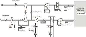
chamber.jpg
 

Attachments

  • test.zip
    230.4 KB · Views: 18
thank you for the answer, but this is a little bit too many complicated for me. Like in ob1 the last rung (why it has to be the last one?). you are calling fc4 from ob1, and those adresses DB101.DBX30.1 are not known to me.

if you just can make fb41 or fb58 which is chasing the setpoint lets say 24 degrees. has its limits. when i set the piw (lets say PIW256) as the setpoint or process variable it stays red like wrong adress? why?
 
I don't know that a Siemens PID loop can be any simpler than the library example I posted.

For the red, try this: Declare PIW as an INT format in your symbol table.
 
Like in ob1 the last rung (why it has to be the last one?).

The last rung of the example program contains a reset of the bit used for First Scan. This bit is set in OB100. We only want the bit to be on for one scan at the first scan...

those adresses DB101.DBX30.1 are not known to me.
Read the network titles:
PID LOOP MANUAL SELECTION BY WinCC
PID LOOP AUTO SELECTION BY WinCC

The DB101.xxxxx addresses are bits that are set from a WinCC SCADA system. The posted code is for example only...

when i set the piw (lets say PIW256) as the setpoint or process variable it stays red like wrong adress? why?

The input to the PID loop must be an INT format. The default in the symbol table is WORD format. Just go to the symbol table and change it to INT format. You may have to exit and restart the LAD editor after making the change to the symbol table.
 
thank you for the response, still no progress with piw. I assigned a name to piw 128 (VOC sensor). In OB35 I call function FC4. In FC4 I have the network with always ON and always OFF logic and have FB58 (assigned DB58 for it). at PV_IN I put PIW 128 but its still red and it is INT in symbol table and I restarted the whole simatic.
 
The file I posted was from a working program that has run for 7 years. It calls FB41 in OB35 which is set in the hardware configuration of the CPU to run cyclically at 1 second intervals. Then FC4 is called from OB1. Look at my input to the PID loop and backtrack to see why yours does not work.

I will be glad to look at your program to see why your PIW input to the FB41 is red. Post it. You may need to copy your program to library before zipping. Complete S7 programs may be too large to post to the forum. If not, post the program. If too large, create a library file and copy your program to it and then post that.
 

Similar Topics

hello, I am trying to connect the analog proportional regulator from Festo (VPPM-6L-L-1-G18-0L6H-A4P-S1) to automation direct analog output...
Replies
6
Views
1,436
Hi, I am an inventor looking for a way to automate a block-making press I made out of a log splitter. It makes blocks for building homes from...
Replies
11
Views
7,230
VALVE MODEL # 4WRPEH 6 C3 B04P-20/G24K0/A1M VALVE MODEL #...
Replies
6
Views
5,956
Have a question about controlling a 4-20ma steam valve by the use of a temperature process controller instead of a plc. This is something that we...
Replies
8
Views
6,386
Anyone ever PWMd the coils of a bang-bang valve? I tried it recently so that I could reduce machine setup-time by eliminating the manual flow...
Replies
41
Views
5,162
Back
Top Bottom