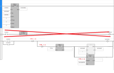
Ramping PWM pin on Micro 820

Join Date
Jan 2024
Location
Denver
Posts
2
Hi All,

I came up with this for ramping the PWM pin on the micro 820. I'm new to ladder logic so I am not sure if this will even work? Once xmotoron is set high, it should pulse pin 6 as long as neither home/end prox are triggered in tandem with the direction. Every time I trigger xmotoron, it should go through the accel loop until xaxisspeedmax is reached?

Thanks for any input!

https://1drv.ms/i/s!AmGu4mSmjSxdgppQqs7BPwx9yN5-hw?e=uUFIHB

Regards,
DI
 
I have no idea about an 820, never used one but on Mitsubishi the PWM instruction only works on transistor outputs, assuming your plc has transistor outputs then it should work, not sure if the pwm instruction does interrupts (would be needed for fast pulses) if not then it would probably only respond correctly to pulses slower than the scan time & of course the time to switch the output on/off.
 
1) Your code will not work

1.2) it has multiple destructive writes to Boolean accelmotor, which is usually a mistake.

1.2.2) Rung 3 will write a 0 to accelmotor on the scan cycle immediately after it writes the 1 to when xmotron is 1 (button pressed?). So the timer on Rung 4 will never expire.

1.2.3) the xaxisspeed increment is before the timer, so even if Rung 4 executed for multiple scan cycles, it would increment xaxisspeed on every scan cycle instead of at 1ms intervals.

1.2.3) There is no more than one rising edge to the CTU to increment its value, and it is not tied to xaxisspeed, so even accelmotor was 1 for more than one consecutive scan cycle, the CTU would never complete.

2) The ENO of the PWM instruction is not the PWM output, so everything to the right of the PWM instruction on Rung 2 is not going to work.

2.1) The PWM controls _IO_EM_DO_06 directly; the program does not need a Coil to write to it.

2.1) See this youtube by @Tim Wilborne for handling the prox and direction inputs.

2.2) If the frequency and duty input parameters to the PWM instruction are "frequently" changing while the Enable rung into the PWM instruction is True, the PWM output channel _IO_EM_DO_06 stays off.

2.2.1) I did an experiment where the frequency and duty were derived from an analog input, and the noise (over time) in the analog input kept the PWM instruction from driving the PWM output channel. I had to toggle the enable on then off to get the PWM to follow the updated parameters. I don't know

  • the quantitative value for "frequently"
  • if this is an issue if only the Freq or only the DutyCycle are being updated "frequently" over time.
The image attached below is an alternate approach that might work; it uses the canonical Start/Stop Circuit pattern (see here https://www.contactandcoil.com/patterns-of-ladder-logic-programming/startstop-circuit/). The code to handle the direction and prox inputs will need to be added; see the video mentioned above.
Untitled.png
 
Final warning: the Micro800 and CCW line work for most things, but it is very Fisher-Price; anything complex, beyond simple relay logic and such, may or may not work as one would expect; I would not expect what you are trying to do to be simple, but I would also not be surprised if it were possible to discover a workaround that was good enough.

Welcome to the forum.
 
Hi Brian,

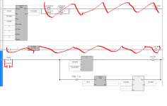
Thanks so much for your reply. I did try to follow Tim's video originally, but clearly made some mistakes. That being said, I tried to address everything in your comments above with the exception of (2.2). Hoping discrete frequency changes at specific timing does not have the same issue you came across.

Please see this picture and let me know if this might work a little better? I will organize the home/end prox sensor to turn off the xmotoron input in seperate code.

https://1drv.ms/i/s!AmGu4mSmjSxdgqIuo5zGTYDuAgfaZw?e=Cs3o14

Thanks,
DI
 
The bit accelmotor2 will not stay on for more than one, and possibly two, scans cycle after xmotoron is released in the updated code; see comment 1.2.2 in my earlier post.

Watch this video series (). Then watch it again and again until the light bulb comes on. PLC programming is primarily about time, and the scan cycle is the clock, so understanding the scan cycle is the most important aspect needed to understand PLCs. I can look at your code an immediately recognize where the problems are. When you are doing something straightforward like incrementing a value, and you have close to a dozen instruction, with half of them keeping the loop alive, it is time to look for a different approach.

Look at the code in the image below. It uses the Start/Stop Circuit pattern (see here), which is what your code is trying to do. Note the direct path from the Start/Seal-in branches through the only Stop Condition (XIO CTU_1.Q) to the Run Coil (OTE accelmotor). Conditional instructions that should not Stop the circuit must not be in that path. Every instruction in that rung is being evaluated, from scratch, on each and every scan cycle, so something like 1kHz.

Do you have any previous programming experience in other environments, such as C, Python, Java, BASH, etc.? PLCs are a completely different environment. PLCs are like GAWK, or an infinite loop in Perl or Python.

Untitled2.png
 
Also note, the way that is implemented with the CTU, that circuit will increase the motor speed from xaxisspeed to (xaxisspeed+xaxisspeedmax), so xaxisspeed should be 0 when xmotoron is initially pressed. That being the case, it might make more sense to get xaxisspeed from CTU_1.CV.
 

Similar Topics

Hi Guys, I'm new to controls and PLCs and this might have a trivial answer. I have a small project with a PLC and a inverter. The inverter...
Replies
25
Views
3,686
I've got a Yaskawa GPD315 running a belt conv and am having issues getting it to stop in a consistent time. System has a PE that when hit, stops...
Replies
25
Views
7,850
There was no great way to describe the behavior this temperature input is demonstrating, so I attached a video. It ramps, then hesitates, then...
Replies
17
Views
5,255
I'm having some issues with one of our warpers. I'll just put the issue and and see if anyone can help narrow it down for me. As the yarn pulls in...
Replies
14
Views
4,365
I've got a control loop controlling the speed of a pump with a VFD as a function of a flow meter measured GPM. When the GPM is increasing, I want...
Replies
7
Views
1,849
Back
Top Bottom