Reading Position Sensor data on Micrologic 1400 series B using MSG implicit messaging

Join Date
Jun 2015
Location
Delhi
Posts
9
Hello Ken Roach,

Thank you for your quick reply , As informed earlier i want to read P&F Sensor data on Micrologic 1400 series B using MSG implicit messaging. Especially CIP function. I am getting DONE bit in MSG block but i am not getting any data.

Please see PLC logic link attached below
https://drive.google.com/file/d/1UYa9lelgHI_u3EzH6BBsIldGAUD5in_d/view?usp=sharing (All Right given to this link no need to send any request)

Please also find P&F Ethernet/IP gateway detail.
https://drive.google.com/file/d/1aIclnBrGKPdORTwL5zYE81omaCpOCEnN/view?usp=sharing (All Right given to this link no need to send any request)


Our P&F sensor is on RS485 network and we are using P&F make Ethernet/IP interface to convert RS-485 to Ethernet/IP. And in the Ethernet/IP manual it is clearly mention we can get position data directly via Implicit Messaging.

And I hope MLX 1400 Series B PLC supports implicit Messaging.

We are getting MSG DONE BIT but not getting any data, Kindly guide us on this.

AKG
 
Last edited:
Welcome to the PLCTalk forum community, AKG ! I appreciate you posting on the main forum where everyone can participate in the discussion.

My first comment should be a reminder that the MicroLogix family controllers are not designed, advertised, or supported to perform "implicit" data exchange using the EtherNet/IP protocol. Implicit connections are the method used for ControlLogix and CompactLogix controllers to exchange data rapidly on a cyclic basis with devices like I/O adapters, or to exchange Produced/Consumed Tag data with other controllers.

The term "implicit" means that the purpose of the data is agreed upon during the connection establishment, and the cyclic I/O packets don't contain the source or target tag names or object definitions.

By contrast, "explicit" connections are generally done on-demand and include the source or target tag names or object definitions as part of each message.

MicroLogix controllers can sometimes still communicate with devices designed for cyclic I/O communications by using explicit messages to read or write CIP Objects in the target, including the Assembly Object that is otherwise used in implicit cyclic I/O connections.

That is what your first link shows: the MicroLogix program has a MSG instruction that is configured to perform a Read Assembly function to read Class 0x04 (assembly), Instance 0x65 (usually an Output Assembly), Attribute 0x03 (the actual assembly data), with size 4 bytes.

When testing messaging logic, I recommend configuring the MSG to be triggered by a test bit that you toggle manually from RSLogix.

Once you have verified that you have communications working, I recommend a repeating timer that executes the MSG instruction periodically.

I do not recommend using logic like your screenshot shows, which re-triggers the MSG instruction as fast as possible. That sort of logic makes it very difficult to diagnose any problems with the MSG (because the error code is cleared as soon as it is re-enabled) and it can overload the communications resources of the controller.

If you really do need a message to execute as fast as possible, then you probably need to migrate the project to a CompactLogix that does support cyclic I/O connections on EtherNet/IP networks.

I have not used those Pepperl + Fuchs sensors or the EtherNet/IP gateway whose user manual you posted a link to. I will take a look at that shortly and give my thoughts/opinions.
 
WCS = "Weg Codier System" (German) = "Position Encoder System".

WCS are linear absolute position encoders with a high-speed RS-485 based connection to an industrial fieldbus network gateway. It's a design that's been around for many years and is particularly reliable and rugged.

The EtherNet/IP fieldbus gateway documentation (linked to above) shows that the I/O Assembly objects are very ordinary Assembly Instance 0x65 and 0x64, and that their sizes differ with the number of connected encoder read heads. For a single encoder read head, the size is 4 bytes for both Input and Output assemblies.

Input Assembly = 101 (decimal) = 0x65 (hex) = data Produced by the WCS and Consumed by the ControlLogix, and placed in Input (Modulename:I.Data[0-7] tags.

Output Assembly = 100 (decimal) = 0x64 (hex) = data Produced by the ControlLogix from Output (Modulename:O.Data[0-7] tags and Consumed by the WCS.

If the WCS places data into the Input Assembly (instance 0x65) even when there is no cyclic I/O connection established, then the MSG instruction shown in the screenshot *should* work.

But some devices don't use the I/O Assembly values until a cyclic I/O connection is actually in the established state. Or they don't do so until a Configuration assembly is written. Or they don't put anything in the Input assembly until they receive data in the Output assembly.

Implicit messaging with a MicroLogix is not documented in the Pepperl + Fuchs WCS fieldbus gateway document.
 
Last edited:
If this were my system, my next steps would be:

1. Simplify the messaging logic so that have manual control over the MSG instruction triggers and can carefully examine the .EN and .DN bits, and the .ER/.EXERR error values.

2. Send a Write Assembly command to Assembly Instance 0x64 of length 4 bytes (and content all zeroes), to see if the WCS will behave as though it is running a cyclic I/O connection when it receives a message addressed to that Assembly.

3. Send a Write Assembly command to Assembly Instance 0x04 of length 0 (or length 1 if it won't accept a zero) to see if getting a Configuration Assembly write is part of how the WCS starts running its I/O Assembly objects.

4. Ask Pepperl + Fuchs for an example of using this device with a MicroLogix 1400 controller.

5. Configure and test this device with a ControlLogix or CompactLogix.
 
Hello Ken,

Thank you for quick response and Sorry for late reply from my side i was on remote site from last few days.

You correctly said that MLX controller is not supporting Implicit messaging. Recently i found one MLX 1400 document where it is clearly written that
" The Micrologic 1400 supports Ethernet/IP™ communication via the Ethernet communication Channel 1. In addition, either Modbus TCP or DNP3 over IP
can be enabled for Channel 1. You can connect your controller to a local area network that provides communication between various devices at 10 Mbps or 100 Mbps. This port supports CIP explicit messaging (message exchange) only.The controller cannot be used for CIP implicit messaging (real-time I/O messaging)"

We also checked with P&F they have not used this WCS-EIG Gateway module with MLX PLC , Yes they have used with ControlLogix and it is working with CLX platform.

Apart from above one of our customer used another model WCS3B-LS510 , this model is with Ethernet/IP port (in this case Gateway WCS-EIG is not required) This WCS3B-LS510 is working with MLX 1400 on messaging.

As per your suggestion i will modify my logix & trigger with manual bit.

Thanks again for your support.
 
Is the PLC code for WCS3B-LS510(working) same as WCS-EIG3109(non-working)?
Can you put up that code.
 
Yes, As i said earlier one of my customer is using WCS3B-LS510 with MLX1400 and it is working. Please find below link of Messaging logic which i received from customer. (Please also note that this logic is working with MLX 1400 but customer had complained us that sometime he is facing problem like he is not getting data for few seconds. So that why we propose them WCS-3B-EIG gateway module.

https://drive.google.com/file/d/1KLVC-ysxZY_HMA0fwrIQCQdEemU-PANU/view?usp=sharing
 
Have you tried what Ken suggested? do a write first before a read.

For the customer who currently using WCS3B-LS510, I would suggest to change the logic to read on the needed basis only AND correcting size in byte to 4
 
Last edited:
The WCS3B-LS510 documentation shows similar, but not identical, configuration and functionality to the WCS-3B-EIG on EtherNet/IP.

In particular it shows that Assembly Object Instance 1 supplies a 4-byte Position value, while Instance 100 (0x64 hex) supplies a 7-byte assembly that includes position, velocity, and status data.

I would have to carefully examine the logic, and probably capture the traffic with Wireshark, to give you an opinion on why the customer using the -LS310 is experiencing "not getting data for a few seconds".

WCS3B_LS510_Assembly.PNG
 
WCS PLC Messaging Logic

Hello Ken,

Thank for your valuable advice as per your advice i have made a PLC logic please find below for your review.

We have sent Hardware (WCS & PLC) to customer site. I will send this logic to my engineer for testing who is already at customer place.

I have small doubt, why "Write Assembly command to Assembly Instance 0x04 of length 0" is this ok?

Please have a look on my PLC logic and advise.

AKG
 
WCS PLC Logic Testing

Hi Ken,

We have tested the above PLC logic today but result is same.

Please see the test report.

Step One (RUNG#1 Writing to Output Assembly 0x64) We got DONE BIT in MSG instruction but nothing happened (Pls see image#1).

Step Two (RUNG#2 Writing to Configuration Assembly 0x04) We got Error in MSG instruction (Pls see image#2).

Step Three (RUNG#3 Reading from 0x65 Input Assembly) We got DONE BIT in MSG instruction but nothing happened (Pls see image#3).

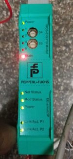
Also see the LED STATUS of WCS-EIG310 Module & Position Sensor (Read Head) WCS3B-LS221(RS-485).

Please note that LED STATUS of EIG module (State LED) is blinking RED & GREEN continuously.(LED status meaning of RED/GREEN is not mentioned anywhere in the manual) it seems that data from sensor (WCS read head) to EIG module is not transferring.

Please see the EIG module LED status & WCS sensor LED status also and advice.

AKG

1.PNG 2.PNG 3.PNG EIG module.jpg WCS Sensor  Module.jpg
 
Unfortunately with a general error indicator on the WCS-EIG310 interface module that does not include an error number display, I cannot guess what the problem is.

You will have to work with Pepperl + Fuchs to diagnose the problem indicated by the red/green flashing STATE indicator.

It's good that the Read message works, but of course it's not unusual that a faulted device or one that is not properly connected to the encoder will not return valid data.
 
How many readers? Looks like both switches set to 0.
Both read & write use same N7:0, bad programming.
Ensure only one Toggle bit is ON at a time.
 
Great point being thorough on the settings.

My reading of the WCS-EIG310 User Manual is that rotary switch S5 is unused, and rotary switch S4 = 0 means "1 read head without velocity output".

The read head itself should be configured for Address 0.

That logic is clearly just for testing; I agree that in a real program you wouldn't use the same N7 register for both read and write, and you wouldn't use MSG control blocks scattered around the controller.

Since the MSG that reads the WCS input data assembly is completing without errors, the problem is that the data payload is evidently all zeroes.

With no error code and the read head address as zero, and no position value and no velocity value, then I think all zeroes is a valid data assembly.

I suppose he should check the DIP switches on the read head itself to be sure they're set up for the correct address 0, and the desired data rate and RS485 terminator.

Disconnect the cable to the read head and see if any of the data or indicators change, too.
 

Similar Topics

Hello I have a s7-1200 and I would like to read the tags present in this controller with my controllogix controller. The two controllers don't use...
Replies
5
Views
145
Hi all, i have 8 CJ2m plc units that show different numbers on the plc display and i am stuck on reading the info. my unit has an ip address of...
Replies
3
Views
100
Hi Everyone, I am not proficient in RSLogix 500 so I have a question regarding the evaluation of N7:0 data as an input. So as I understand in...
Replies
1
Views
87
Trying to setup a message read via Ethernet. I have the path setup as 1, 1, 2, 192.168.66.10 I get an error code 1, ext err 315. I am beating...
Replies
9
Views
233
Dear all, I don't know why setup of password became challenging and weird. After setting up the password and try to upload the ladder from the plc...
Replies
3
Views
174
Back
Top Bottom