Rs500 sqo hold position after stop and restart

Joewiza1

Member
Join Date
Feb 2024
Location
North Carolina
Posts
6
Hello I am trying to make a program work with a sqo instruction .The process has 5 steps ,and a starting step of zero.There should be 8 sec between each step,and I am using a RTO for that.My problem is whenever I stop the process and restart it the process goes to the next step,but holds the time from the previous step.I will post a pic of my latest attempt I will try to combat this problem .I am wondering if anybody can tell me if this will work ,or can tell me the proper way?
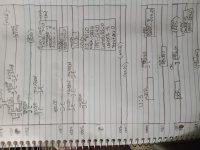
20240211_112121.jpg
 
Reset the timer on your stop bit if you want the first step to take 8 seconds again.
 
So if I am on step two and the timer has timed for 4 seconds when stop pushbutton is pressed once I hit restart it goes to the next step but the timer is still at the accumulated value of the last step so it will only time for whatever is left on the timer.i need it to stay in the position it was in at before the stand retain the value of timer after restart
 
Also, rung 0004 will never call (JSR to) U:3, because

  • if the XIO B3:0/0 evaluates to True
    • because B3:0/0 value is 0,
  • then the XIC T4:0/EN will evaluate to False
    • because T4:0/EN will have been assigned a value of 0 on rung 0002.5
And vice versa.
 
Also, rung 0004 will never call (JSR to) U:3, because

  • if the XIO B3:0/0 evaluates to True
    • because B3:0/0 value is 0,
  • then the XIC T4:0/EN will evaluate to False
    • because T4:0/EN will have been assigned a value of 0 on rung 0002.5
And vice versa.
So maybe do away with the b3:0\0 on rung 4?
 
So if I am on step two and the timer has timed for 4 seconds when stop pushbutton is pressed once I hit restart it goes to the next step but the timer is still at the accumulated value of the last step so it will only time for whatever is left on the timer.i need it to stay in the position it was in at before the stand retain the value of timer after restart

Then not sure what you're trying to achieve with the JSR then (that doesn't get called anyway) where you are forcing outputs.

And as I mentioned, if you want the timer to reset, then reset it on loss of your B3:0/0.
 
So maybe do away with the b3:0\0 on rung 4?


That depends on the conditions under which you want SBR U:3 to be called. If you want SBR U:3 to overwrite O:4.0 on any scan cycle when both the B3:0/0 value is 0 and the timer is timing but not yet done, then yes, removing the XIO B3:0/0 would do that.

Also, I notice that the Start PB is I:5/0 in rung 0001 of the main program file, but Start PB is I:3/0 in Rung 0000 of program file U:3.

Can you give summary of what you are trying to achieve here? Because it looks like, with the current code:

  • If Hold value is 0, then O:4.0 value should always be 0
  • If the Start PB value is 0 (is pressed?), then write a value of 1 to Hold, as long as the Stop and E-Stop values are both 0
  • If Hold value is 1, then
    • write a value of 5 to O:4.0 (in U:3) on any scan cycle when the Start PB is held depressed
      • This assumes the XIO B3:0/0 on rung 0004 has been removed.
    • start a repeating 8s timer, and
    • on each single cycle when when that timer expires
      • Increment the position of the SQO R6:0, and
      • write the value of the new N7:[R6:0.POS] to O:4.0
 
... My problem is whenever I stop the process and restart it the process goes to the next step,but [the RTO] holds the time from the previous step.I will post a pic of my latest attempt I will try to combat this problem .I am wondering if anybody can tell me if this will work ,or can tell me the proper way?


The simplest thing to do would be to change the RTO instruction that uses T4:0 to a TON instruction; then T4:0 would reset its accumulator to 0 any time the value of Hold becomes 0.


That would also eliminate the need for Rung 0002, as the timer would reset on any single scan when it expires (i.e. when T4:0/DN value becomes 1)
 
That depends on the conditions under which you want SBR U:3 to be called. If you want SBR U:3 to overwrite O:4.0 on any scan cycle when both the B3:0/0 value is 0 and the timer is timing but not yet done, then yes, removing the XIO B3:0/0 would do that.

Also, I notice that the Start PB is I:5/0 in rung 0001 of the main program file, but Start PB is I:3/0 in Rung 0000 of program file U:3.

Can you give summary of what you are trying to achieve here? Because it looks like, with the current code:

  • If Hold value is 0, then O:4.0 value should always be 0
  • If the Start PB value is 0 (is pressed?), then write a value of 1 to Hold, as long as the Stop and E-Stop values are both 0
  • If Hold value is 1, then
    • write a value of 5 to O:4.0 (in U:3) on any scan cycle when the Start PB is held depressed
    • start a repeating 8s timer, and
    • on each single cycle when when that timer expires
      • Increment the position of the SQO R6:0, and
      • write the value of the new N7:[R6:0.POS] to O:4.0

No the start pb is I:3/0 for both my handwriting is just sloppy.Ok I will try that.So the pseudocode is I will have 5 different outputs.They each stay on for 8 seconds then move to the next step.My counter must retain its accumulated value if stopped ,and the position must not move to next step after the restart.I am sorry this is not my job it is for a class project .I must have a mov instruction ,and a jsr.That is why the jsr is in there.I know I must look like a complete noob.I am sorry.I just don't have anyone to ask for assistance.
 
The simplest thing to do would be to change the RTO instruction that uses T4:0 to a TON instruction; then T4:0 would reset its accumulator to 0 any time the value of Hold becomes 0.


That would also eliminate the need for Rung 0002, as the timer would reset on any single scan when it expires (i.e. when T4:0/DN value becomes 1)

It has to be a rto
 
I suggest you read the description of the TON (here*) and RTO (here*) instructions. Pay particular attention to

  • the timing diagrams (at the bottom of p. 79 for RTO and the bottom of p. 98 for TON)
    • Note the difference in what happens to the .ACC attribute when the rung condition in transition from 1 to 0 in the cases where "the timer did not reach .PRE value"
  • the flow charts

* Those links are for Logix/Studio 5000, but the timers operate in essentially the same way as RSLogix 500; the only significant difference is that the 5000 timers only have a single timebase (1ms i.e. 0.001s) so there is no Timebase input parameter, but that does not effect the timer-internal logic and operation conceptually.
 
It has to be a rto


Why? The only reason to use an RTO is to retain the accumulated time when the rung-in-condition is False, and you state in Post #1 that that retention of accumulated time is an undesirable behavior.

If there is indeed some other reason, then @robertmee told you what to do: reset the accumulated time to 0 when the value of Hold is 0.
 

Similar Topics

I am reasonable familiar with with rs500 sequencers (by no means an expert) but this format of addressing the file on a SQO has me stumped...
Replies
3
Views
1,532
I have upgraded an old RS500 project to Studio 5000, it has thrown multiple errors which I am currently working through. I have looked through...
Replies
8
Views
1,725
I am working on upgrading a system with a ML1500 that uses a 1769-SDN DeviceNet Scanner to a CompactLocix L24ER-QB1B. Due to cost, I need to...
Replies
2
Views
1,403
I have been ask to check if we can have both English and Chinese in the same I/O description text window and rung comments. I could not Chinese to...
Replies
2
Views
1,212
Hi all, Here's an easy one. I've been asked to change a mitsubishi FX plc to a AB1400 using the same program. My customer has emailed me the...
Replies
5
Views
1,626
Back
Top Bottom