RSLogix500 Output will not energize

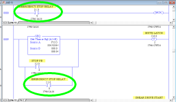
The Emergency Stop Relay sets a MCR zone when it is ON


On the last branch you activate the OTU if it is ON also.


The OTU should be if it is OFF - BUT: If it is OFF the MCR zone will not be scanned so rung 9 should be moved to after the end of the MCR zone.


Also, it takes a few less words of memory and a couple less clicks of the CPU scan to extend a branch down rather than nest a second branch.

Capture.PNG
 
I don't know if you are doing this, and believe me I know how easy it is to go down this road, but asking yourself why an OTL does not write a 1 to its operand when that OTL's input rung is true is a waste of time; much more useful questions are "what is the state of that OTL's input rung" and "what was the value of that output immediately after the rung with the OTL?"

The tricks to diagnosing problems like this are
(i) to assume the PLC is doing exactly what you are telling it to do in the program logic, and
(ii) to get stupid (as stupid as the PLC), and
(iii) to discard any notion of what you want or expect it to do or think it is doing.
The primary problem is to discover why it is doing what it is doing (as opposed to what you expect it to do, which never matters); the tricks above, especially (iii), make your diagnosis a deterministic process and make it far easier to discover that why. For example, once you confirm that those two OTL/OTU instructions are the only way the O:6/2 bit can be written, then your investigation is reduced to those two rungs and a series of binary questions that are relatively easy to answer: will an upload from the PLC give you the same logic (sans comments) that you think is in the PLC; what are the input conditions on those rungs; are those rungs executing; etc. What diagnostic logic can be added and/or steps be taken to answer those questions?

Once you know that why, it will be easier to get it to do what you want it to do.

That's the general idea.

As a specific diagnostic, you could write an otherwise unused bit with an OTE on a branch in parallel with the OTL on the latch rung (0008), and write another bit on rung 0009 in parallel with the OTU. Then viewing those other bits tells you a lot about the rung e.g. whether it is running (cf. @OperaGhost's suggestion).

Sidebar: the logic you have added in the two rungs 0008+0009 is a Start/Stop Circuit pattern, which operates almost identically with the single rung in the image below.
Untitled.png
 
Sidebar: the logic you have added in the two rungs 0008+0009 is a Start/Stop Circuit pattern, which operates almost identically with the single rung in the image below.


Except that in your example you changed the operation of the Emergency Stop Relay.


In the OP's program it has to be TRUE to enable the MCR zone (13:0), and in his OTU rung (13:9)if it is TRUE it unlatches the output.


His output is never turning on because it is turned off every scan on the next rung when the Estop relay is ON, plus when the Estop relay is not on the MCR zone is deactivated. That rung needs changed so XIO Estop unlatches.

EDIT: Plus when the Estop input is off the MCR zone will not be scanned to process the OTU That rung needs moved outside the MCR zone.

CaptureOP.PNG
 
Last edited:
Forest and trees, d'Oh!


I saw your earlier post, and had a feeling the fundamental problem was the MCR, but I skimmed and didn't fully grok it.


Thanks!


The only thing I'm not sure of, and want to test, is the operation of a latch in a MCR zone.


When a MCR zone is OFF all OTE outputs are shut off. I'm presuming a latched on output would stay on until the OTU is processed.


I want to test and see of a OTL latched output stays on or does turn off.


I've never used a latch command in a MCR zone.


When I get home I'm going to throw a test in my home automation SLC.
 
JIC someone else was wondering about the MCR and latched bits.


When the MCR is activated the latch and unlatch output works by the HMI buttons as it should.


If the MCR is toggled OFF the check of the bit controlling the MCR does NOT unlatch the output in the MCR zone, neither does the Stop HMI PB. It stays ON until the MCR is active again and the Stop pressed. Not even the first run through unlatches it.


The OTU rung outside the MCR zone always works.


Plus, in the OP program none of the other outputs in the MCR zone are latched, so those would be shut off when the MCR was disabled.


Plus#2, this goes against the advice given here many times to NOT latch PLC outputs because you need to think of EVERY way needed to unlatch each one - and that could be half the program itself checking for hundreds of ways to unlatch outputs.

Capture.PNG
 
JIC someone else was wondering about the MCR and latched bits.

To reinforce/expand on what you discovered... MCR zones when true, allow everything within that zone to run normally (unaffected). When the MCR zone is false, all outputs in the zone are set to their false state. For example:

  • An OTE will turn its bit off
  • OTL and OTU instructions will do nothing
  • A TON will reset
  • A RTO will stop timing but not reset
  • A TOF will begin timing
  • A CTU or CTD will not count but will not reset

So whatever those instructions do when they are false, that is what they do inside a false MCR zone.

OG
 
So the first of a pair of MCRs essentially sets the left-hand rail to False (or grounds the left-hand rail, if you prefer that analogy) until the second MCR of a pair, but the rungs are still evaluated.

A better option (CAVEAT: depending on what is intended) might be a JMP instruction, that JuMPs over those rungs i.e. prevents them from being evaluated at all.

[putting on a helmet and moving to my bunker now ;)]
 
A TOF will begin timing


Interestingly, it does IF the ladder is being called while the MCR is off.


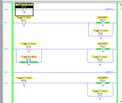
I put a conditional jump in Ladder 2 to this MCR test ladder and when the TOF is timing (due to either the MCR off or the rung enable bit off) if the JSR is disabled the TOF resets, /DN goes OFF and .ACC changes to the .PRE value.


EDIT: Plus if the JSR is disabled while the MCR is ON the timer resets without starting timing.
 
Last edited:

Similar Topics

So here's my situation, I have been tasked with modifying the logic to mimic a button press in the PLC. I have two identical machines however one...
Replies
6
Views
541
So i have an allen bradley rack (2080-LC50-24QWB), i have it connected through ethernet. I dont have an offline program so im trying to upload...
Replies
6
Views
682
Hi Everyone, I am supporting a system which runs on a SLC 500 (1747-L532). A fault has developed whereby the output state of some digital outputs...
Replies
10
Views
1,000
Hello, I am currently taking a course on plc programming and in the course rslogix 500 is being used. I am however having a problem since it keeps...
Replies
4
Views
1,703
Hello experts, I am just starting with AB programing, I have a questions regarding a compare done in an old RSlogix500 and causing me issues when...
Replies
5
Views
1,941
Back
Top Bottom