RSLogix500 PID toruble

Join Date
Mar 2009
Location
Valencia, Carabobo
Posts
11
Greetings everyone! I'm designing the automation for a Flame Control process, but I;ve been having some trouble on the programming and even more with the PID block. The thing is that I've tried everything but nothing makes it work. I've been reading very much on this since long time ago, and have been getting no results with it. Can anyone give me a help on this?

I've read a lot of posts that are here and many manuals of the AB web site... But still nothing... Please help me on this...
 
Can you post your code (.RSS file, zip it first then post) and tell the forum exactly what is or is not happening. The more info you give the better the help.
 
I/O Config

My I/O Conf is the next:

1747-l541 5/04 CPU
1746-IM8 8-Input 200/240 VAC
1746-NT4 Analog Thermocouple Input
1746NO4I Analog Current Outpu
1746-OAP12 12 Triac Output

Rack: 1746-A7 7-Slot Rack
Power Supply: 1746 - P1

I'm still working on the programing to make all the rest things to work... I can post it later when I have it done, or if you don't mind I can post it as it is.
 
Program Code

The description of every item is made in spanish, as I said, It's not done or finished. I'm posting the last version I have (Control17.rss). The PID block goes where is the title in green that says: "MODUTROL por escala". I have there some commands that I know there totally wrong that I first thought i could work. These are the lines from 0026 through 0031. Those have to be substituted by the PID block. If you have any questions, I'll be checking the thread regularly to answer them. Besides the flame control code, there's a file (PID.RSS) I was using to try a PID control with a Slider, but never worked...

Thanks
 
Greetings alconst ...

let’s start with the very basics of the setup in your PID.RSS file ...

first of all, you’re trying to get your input signal (PV) from a DIGITAL input module (1746-IA4) ... that really needs to come from an ANALOG input module instead ...

you’re trying to send your output signal (CV) to a DIGITAL output module (1746-OA8) ... that (probably) needs to be an ANALOG module also ... (possible exception: MAYBE you could use a “time proportional output” – but I doubt that’s going to give you the resolution you need) ...

take care of those issues and then we’ll try to go further ... (note: we can’t really tell you how to set up the scaling values until we know more about the specific hardware you’re going to use ...

gettting to your CONTROL17.RSS file - there's no PID instruction in there ...

I can’t read the Spanish – so I’m just guessing here – but it looks like you’re trying to write your own control ... if so, double check the SCP in file 2 – rung 31 ... notice that your Input Min and Input Max are set for a range of 0 to 100 (percent?) – but N7:0 contains a value of 13104 ... maybe this “scaling” issue is part of your problem ...

I notice that slot three of THIS program does contain an analog output module ... is that what you "meant to" set up in the PID.RSS program? ...
 
Last edited:
Ok... I have no Hardware yet, because this is only the design. So I'm writing it until it works and simulating it. What I was doing on the "PID.RSS" was trying to make the PID block to work since I really don't know how to, so this file is only for testing on how it can work. I can change the digital modules to analog ones, but I think will not make the PID block to work (I just think this, not sure of it).

About the "CONTROL17.RSS", yes I was first trying to do a control myself, until I found that it could be easier with a PID block, but I've been having some trouble. This is the first time I use this software, and been learning while working...

I was looking for a PID block tutorial on the web but still haven't found anything... And people here don't know very much about it either... And today (after a few months of knocking my head with the PC and the manuals, forums, etc) thought of writing my problem here.
 
OK ... that makes a BIG difference ... I'm teaching all this week - but I'll try to put in a quick getting started program for you (maybe this afternoon) ... you won't be able to actually "TUNE" the PID - but at least you'll be further along than you are now ...

stay tuned ...
 
this is as much as I’ve got time for today ...

load the .RSS file into an SLC processor ... you may have to change the chassis size – and move the input and output modules to slots that match your (chassis) hardware ... make sure that the modules are “turned off” (not “enabled”) on the I/O tab of the Status File ... this lets you override the signals from the input module – so that you can manually type in any signal that you want it to “see” for experimental purposes ... also it lets you run the program without actually having the hardware present ...

I’m simulating a temperature control loop which ranges from 0 to 500 degrees F ... at the beginning of the graph, I’ve entered a signal of 5898 at I:7.0 which equates to 100 degrees ... this is too cool for my setpoint of 250 degrees ...

important: how cool is “too cool” ? ... 100 divided by 500 equals 0.20 of full scale ... setpoint of 250 is 0.50 of full scale ... Error is 0.50 minus 0.20 equals 0.30 of full scale ... note that CV at this point of the graph is 0.30 of full scale ...

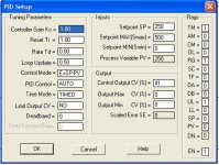
I have Kc set for 1.00 (entered as 100 at N10:3) ... so ... output of PID is 0.30 of full scale at these conditions ...

then I set the Integral action for 1.00 minutes per repeat (entered as 100 at N10:4) ... this makes the CV ramp upwards ...

then I set I:7.0 to 9831 to simulate an instantaneous rise in PV from 100 degrees to 250 degrees (now “on target” at setpoint) ... note that Integral action quits ramping the signal up ...

suggestion play with different settings at I:7.0 (or YOUR corresponding location) ... play with different settings for Kc and for Ti (skip Td for now) ... notice how PID responds – and try to work out WHY it acts the way that it does ...

note that you will NOT be able to “TUNE” the loop – since there is no actual feedback from the system – only what values you manually enter in for the PV signal ... but experimenting with this MAY be helpful as you try to figure out what’s going on ... with the PID ... wish I had more time to play ...

good luck with your project ...

trypid2.jpg
 

Attachments

  • new_pid.zip
    17.4 KB · Views: 80
Ok... I tried to open the file you sent me, but it gave me the error: "Error decompressing file". What version of RSLogix do you have? I use 3.0. In case you have a latest version of the software, can you upload some pics so I can work with the PID? Please!

Thak you!
 
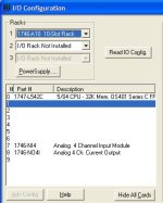
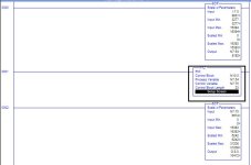
See Pictures below and PDF . The latest Ver. of RSLogix500 is 8.10. time to upgrade.

IOsetup.jpg Ladder.jpg PIDSetup.jpg
 

Attachments

  • NEWPID.pdf
    20.5 KB · Views: 89

Similar Topics

I have two questions: When you open the settings for the PID you have the option of doing manual and auto does manual use the values entered and...
Replies
2
Views
1,754
Dilemma..PID Instructions. I've read through back and forward and read Through again and I still don't quite grasp the setup of the outer face...
Replies
7
Views
2,842
Setting up a PID instruction to control the temperature of oil in a small tank. First time using PID instruction. The heaters are 480VAC...
Replies
4
Views
2,538
I have been troubleshooting a system containing PID's that doesn't perform correctly (it's nothing dangerous) the setup screen shows a setpoint...
Replies
3
Views
3,106
I am tuning a PID loop on an SLC5/05 processor. The problem is- when viewing the PID setup window (while running), the scaled error doesn't...
Replies
3
Views
4,506
Back
Top Bottom