S7-1200 - CarloGavazzi EM340 Modbus Comms

NoName

Member
Join Date
Sep 2003
Location
Domžale
Posts
273
Hello all.
I am trying to read out the values from a Carlo Gavazzi EM340 energy analyzer via Modbus communication.
The S7-1200 PLC has the CB1241 module that is connected to the EM340 unit.

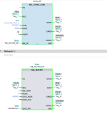
So I configured the Modbus_Comm_Load block and the Modbus_Master blocks (I've attached a picture of the configuration).
On the Modbus_Comm_Load block when I set the Req input to ''1'' the status Changes from #7000 #7002 and goes back to #7000 but I don't get a Done signal.
Nontheless I tried the Req input on the Modbus_Master block and then I get the following error in the diagnostic buffer of the PLC.
-

Temporary CPU error: Area length error in FB 641
affecting OB 1 execution
write access DB area
Incorrect address, operand ignored
Processing will continue (no OB processing)

PLC_1 / PLC_1


Internal address details: Caddr=16#00000CD0, area: DB area, addr: 0
-
And the Modbus Master block outputs the following error: #8281
This is from the help

16#8281
Negative acknowledgment when writing module
Check the input at the PORT parameter.
You can find more detailed information on error causes in the static parameters Send_P2P.WRREC.STATUS or Receive_P2P.WRREC.STATUS, and in the description of the SFB WRREC.
Any info what could be wrong? The Port number is correct, so I don't know what else to try...
Cheers
Aleix
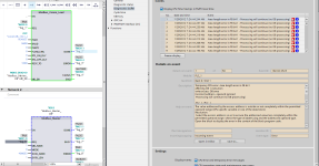
modb2.png
 
Double check the port through PLC tags and switch the tab to system constants. Most likely you are right, but I checked a program that I did which uses CM instead of CB interface and that has the number 269. Most likely it's assigned as first module, but I don't have a CB to check how the numbers are assigned.

Also, try changing the MB_DB address to just %DB3, rather than the MB_DB part of it, as I think that's what the diagnostics is trying to say.
 
Hello,
Made some progress...

Now I used blocks from the Modbus folder in the communictions menu. Before I used blocks from Modbus (RTU) folder.


Now the MB_COMM_LOAD block gives me ''1'' at Done when I set the REQ to ''1''.


But the MB_MASTER block still doesn't get data...When I set Req to ''1'', busy output goes to ''1'' and nothing happens after that. The status of the block stays at #0000. I've attached the picture of the code.


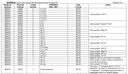
For the begining I just want to read the first holding register at 400001, which is an INT32 as the Modbus table describes. So a Dint. Correct?

So at the Data_Addr I set 400001 and at Data_Len I set 2. I presume that this is corect.

modb_table.png modb3.png
 
I allso noticed that when I set the REQ to ''1'' on the MB Master block the TxD light flashes on the CB module, so I guess that data is sent to the energy meter, but it doesn't reply... Could it be the Connections.


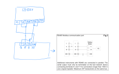
This is how I have it connected at the moment...(see attached picture)


Cheers
Aleix

Modbusconn.PNG
 
Your attachment shows that you should be using 300001 (input word) rather than 40001/400001 (holding register). Usually, you'd be looking for the holding registers but I have come across instruments that don't write their inputs to the holding registers.

Also, trying assigning the DONE tag on the comm load to the EN of the master. I seem to remember having a similar issue where it won't change the parameters of the master block while enabled, even though you're not yet calling the REQ input.


Hello.
This was the reason I used 400001 insted of 300001 is this.
From the communications manual of the energy meter...
---
IMPORTANT:
1) In this document the “Modbus address” field is indicated in two modes:
1.1) “Modicom address”: it is the “6-digit Modicom” representation with Modbus function code
04 (Read Input Registers). It is possible to read the same values with function code 03 (Read
Holding Registers) replacing the first digit (“3”) with the number “4”.

---


This is the link to the manual of the energy meter where you can see the data table on page 9:
https://gavazzi.se/app/uploads/2020/11/em330_em340_et330_et340_cp.pdf


Edit: I tried also with 300001 but it gives me Error #8189 -Invalid data address value.


Cheers
 
There is excellent Omron software tool called Multiway for testing comms, including Modbus. It is free of charge. I would try with it to see what is happening.
 
Your hand drawing have T connected to B+ on EM340. It should be T to A-.
Is that typo on your drawing or wiring error?


Biasing you have allready on Siemens side, so it should be ok.


Lastly.

EM340 is RS485.

Siemens Com_load_block initiate by default RS232.


Have you selected RS485 with com_load_instance static changing mode value before init?


Mode have by default = 0 (RS232)
2wire RS485 is mode 4.


You have readed the PtP manual? 📚


Static tags in the instance DB

MODE (default 0)

Operating mode

Valid operating modes are:
0 = Full duplex (RS232)
1 = Full duplex (RS422) four-wire mode (point-to-point)
2 = Full duplex (RS 422) four-wire mode (multipoint master, CM PtP (ET 200SP))
3 = Full duplex (RS 422) four-wire mode (multipoint slave, CM PtP (ET 200SP))
4 = Half duplex (RS485) two-wire mode 1)
 
Last edited:
Your hand drawing have T connected to B+ on EM340. It should be T to A-.
Is that typo on your drawing or wiring error?


Biasing you have allready on Siemens side, so it should be ok.


Lastly.

EM340 is RS485.

Siemens Com_load_block initiate by default RS232.


Have you selected RS485 with com_load_instance static changing mode value before init?


Mode have by default = 0 (RS232)
2wire RS485 is mode 4.


You have readed the PtP manual? 📚


Static tags in the instance DB

MODE (default 0)

Operating mode

Valid operating modes are:
0 = Full duplex (RS232)
1 = Full duplex (RS422) four-wire mode (point-to-point)
2 = Full duplex (RS 422) four-wire mode (multipoint master, CM PtP (ET 200SP))
3 = Full duplex (RS 422) four-wire mode (multipoint slave, CM PtP (ET 200SP))
4 = Half duplex (RS485) two-wire mode 1)


Hello. Thanks for your input.

I am using a CB1241 RS485 module. Not the CM1241 module. So I cant realy define what you are mentioning.


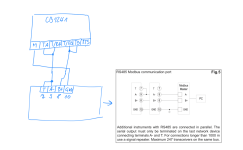
Regarding my hand drawing it's a typo. Terminal 8 and 9 are mixed up. I will post a correction of the drawing.
 
Is there a way to do this in the instance DB? Operating mode is changed in the hardware properties under Device Configuration.

You move value with move-block to instanssi Block's DBxx.mode address before initing com_load.
As it is static area you can read and write it.

Com_load block writes parameters over hardware settings
 
Hello.
See the updated connection scheme.
When I set the REQ inpt on the MB_MASTER block to ''1'', the CB module flashes the TX led, but I don't get anything back from the energy meter...
Could it be something with the wirinng? But for my understanding the wiring is correct as it's drawn on my picture? Or not?ž

Thanks.
Cheers
Aleix

Modb-conn-scheme.PNG
 
Last edited:
It would be very useful to you to have a USB to RS485 converter so that you can monitor the traffic on the RS485 bus. They are cheap and easy to find.

You have made a big step forward by getting the TX light to flash, but obviously you need to find out why the EM340 unit doesn't respond. Sorry I haven't read all the way through the thread, so maybe will repeat things. First stage is the hardware connection, it is worth swapping the As and Bs, it is quick and easy and very unlikely to cause harm. Modbus RS485 is multi-drop, so make sure that you are using the right endpoint and that the EM340 is set to the same endpoint. Check that both systems are using the same baud rate. After that you have to start looking at the registers you are asking for, modbus is a bit frustrating, if you ask for the wrong thing you get no answer, not an error message.

As I say a cheap USB to RS485 will make life a lot easier. To paraphrase 'a life without diagnostic tools is not worth living' :)


edit: nearly forgot the importance of termination resistors, it won't make much of a difference on short runs, but is essential on longer ones.
 
Hello everyone,

Today, I attempted to connect my laptop to an energy meter using Modbus Poll and a RS485 USB converter. Although the connection appeared to be successful - I could see an RX/TX icon on the energy meter's LCD display - I was unable to read the data because I couldn't set a 6 digit address for the holding register in Modbus Poll. Whenever I tried to read the default address (40001), I received a "Read error:Farming error" message.

After that, I connected my laptop to the CB1241 module. However, when I tried to start the connection in Modbus Poll, I received a timeout error. I did notice that the CB1241 module was receiving some data as the RX light on the unit was flashing. When I switched the TA and TB wires, I received a "Write error:Break condition" and a "Read error:Break condition" message. I later discovered that this error can occur if the channels are crossed.


Any thoughts?

Cheers
 

Similar Topics

Hi all, Currently having trouble getting a speed reference to write over modbus to an Omron M1... I can successfully write a run command and...
Replies
6
Views
258
HI i would like to know how to get a variable that will store the amount of times a program has been executed. The issue is I have 3 DBs for 1 FB...
Replies
2
Views
82
Hi, I have attached herewith one image which our programmer has been used in S7 1500 PLC. Now we need to use the same instructions in S7 1200 PLC...
Replies
4
Views
120
commentaire communiqué siemens s7-1200 avec vfd delta ? (cablage et sur tia portal )
Replies
0
Views
139
Hi, I have a 1214 on ip 192.168.0.100. This is connected to other modules through a switch on same network. I need to connect this to a company...
Replies
1
Views
184
Back
Top Bottom