S7-1200 - CarloGavazzi EM340 Modbus Comms

There are two different blocks here.
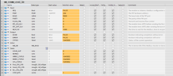
-MB_COMM_LOAD
-Modbus_Comm_Load

I believe OP is using the former, as the mode is not available in the DB. According to the help file, MB_COMM_LOAD can be used with either CB1241 or CM1241, where Modbus_Comm_Load only mentions the CM1241 which is not being used here.

May be worth a try to see if the other block works differently, but I seem to remember having constant errors even though I was using a CM1241.


Hello.
Yes I tried te Modbus_Comm_Load block which is in the Modbus (RTU) folder where there is the option to set the mode, but this doesn't work with the CB1241 module. I tried anyways but it doesn't connect...
 
I have done this setup, I'll try to find time tonight and send selections from my program
/Tim
 
Couple things which you could still check.
Is CB1241 module new one. Remembering that years ago firmware version of PtP and block version needed to match. Thought it was TIA11 or TIA12.
If project had never block version build than firmware it didn't worked. (It had no errors on diag buffer)


I assume that CPU is also pretty new, so this isn't from FW difference. (Modbus com load help files says that CPU FW needs to be at least 2.0 and also PtP librarys needs to be certain between different versions.

This same info isn't sayed on MB com load side, but on behind modbus blocks calls PtP blocks.)


400001 is extended addressing. Siemens has extended address selection on MB_master block parameters, try instead 40001 and 30001 range if you haven't selected extended addressing on master block.


You have MB query lenght 1 int. Is data buffer long enought to save received data?

(1 int is 2 bytes so at least P#DBx.DBX0.0 BYTE 2 lenght for buffer on MB_master block)
 
Last edited:
Also how often you request MB master?
Selected timeout is 1000 (ms), there is also 2 retries.
This means that your actual timeout is 3000ms for slave if master don't get reply from slave.


If you send new MB reguest before this time and earlier query have error then new and old mb query are sended same time to line.
This means collision on traffic and modbus data is corrupted on serial line.
Try retries = 0 and request new query only after 1000ms time is goed (MB master block show error or done pulse on outputs)


You have also double checked EM340 serial baud rates and power booted it if you have changed parameters.


Also sometimes CPU needs power boot after you have loaded first time modbus blocks and hardware to new CPU.
Not sure why, but power booting CPU have repaired non working Modbus test setups after hardware and software download on 300 and TIA.
 
Last edited:
I have done this setup, I'll try to find time tonight and send selections from my program
/Tim

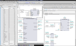
Bare with me since I haven't reed through the topic but I'll post some screenshots from my program. If it helps.

I have the MB_master in a function block that control my modbus sequence. I have posted some diffrent views where you can see roughly how it binds together.

The MB_comm_load is v2.1 and the MB_master is v2.2. You can ignore some inputs on my function block. And on the MB_master is a dataPtrTemp, it is in the end after some code moved to "IN/OUT_data" that you dont have to worry about.

Hope it helps

Modbus RTU EM340.PNG
 
Bare with me since I haven't reed through the topic but I'll post some screenshots from my program. If it helps.

I have the MB_master in a function block that control my modbus sequence. I have posted some diffrent views where you can see roughly how it binds together.

The MB_comm_load is v2.1 and the MB_master is v2.2. You can ignore some inputs on my function block. And on the MB_master is a dataPtrTemp, it is in the end after some code moved to "IN/OUT_data" that you dont have to worry about.

Hope it helps


Hello.
Thanks for shareing.
What I can't understand from your screen shots is that you set 30013 to the IN_dataAdress input and you have the IN_lenght set to 50.
So it reads 50 words from register 30013 onwards? And this two 30013 and 50 are hard coded. How do you fill the entire DB with data?


Also where did you get the number 30013 for the location of the holding registers.


I will try with the same settings that you have on the pictures and see what happens. Will post the outcome. Thanks


Cheers
Aleix


Thanks in advanced.
Best regards.

I read 30013 and length 50, correct.

Reason it looks wierd is that I tried for a while to read directly to the "status" data but it wouldn't allow me. So I had to have a array of only int to read into thus "test" array.

I'm not using all the data that I get so I just move the values I need from the "test" array to the correct place in the "status" data.


30013 I got from the manual of the EM340 https://gavazzi.se/app/uploads/2020/11/em330_em340_et330_et340_cp.pdf
 
Hello.
I tried to read 30013 lenght 2, because I set the PTR to P#m50.0 byte 4, just to test. The Mode is set to 0.


Again just the busy output goes to ''1'' and no data is in the Data pointer...


What is confusing for me is that in the manual the addresses start from 300001 and on...
not 30001.
 
note that the "Modicom" [sic] "addresses" 30001 and 300001 may point to the same register, because that leading digit 3

  1. is NOT part of the Modbus protocol, but
  2. is instead part of an industry de facto convention used by many vendors of otherwise Modbus-compliant software and hardware, and
  3. refers to one of four data (~memory) blocks in the Modbus devices's data organization.
Cf. the Modbus Application Protocol document here:

  • nowhere in that document will you see a reference to the leading digit of that industry convention
  • pay particular attention to the two models:
    • the Modbus data model (Section 4.3 on page 6);
    • the Modbus addressing model (Section 4.4 on page 7).
Descriptions of the traditional and/or de facto, conventions are available here; in summary,

  • Modbus Protocol requests have
    • addresses that run from 1-65536 (data model) ≡ 0-65535 (protocol addressing mode), and
    • the data block is provided by the protocol Function Code:
      • (output discrete) Coils
        • Function Code 1 for reading
        • Function Codes 5 and 15 for writing
      • Discrete Inputs
        • Function Code 2 for reading
      • (16-bit) Holding Registers
        • Function Code 3 for reading
        • Function Codes 6 and 16 for writing
      • (16-bit) Input Registers
        • Function Code 4 for reading
  • The industry de facto convention to define Modbus requests has two parts:
    • A two-part addressing scheme
      • (i) A leading digit indicating the target data block
        • 0 for (output discrete) Coils
        • 1 for Discrete Inputs
        • 3 for (16-bit) Input Registers
        • 4 for (16-bit) Holding Registers
      • (ii) a trailing "address" indicating the position of a single data entity in that data block
        • EITHER an ordinal position, 1-9999 or 1-65536, into the data block,
        • OR a cardinal offset, 0-65535, from the start of the data block
    • A request direction i.e. read or write.
So a

  • Modbus protocol request with
    • MODBUS addressing offset 65535, and
    • Function code 4 (04h, Read Input Registers),
is the same as an

  • Industry de facto convention request with
    • Address 365536
      • 3 => Input Registers
      • 65536 => ordinal of the target in the Input Register data block
    • Read = request direction
That is all prologue. So the first thing you need to figure out is the convention, Modbus standard or de facto industry, and ordinal or offset addressing, used by the Siemens Modbus instruction. Once you have that, configuring the instruction becomes much simpler.
 
Last edited:
Hello.
I tried to read 30013 lenght 2, because I set the PTR to P#m50.0 byte 4, just to test. The Mode is set to 0.


Again just the busy output goes to ''1'' and no data is in the Data pointer...


What is confusing for me is that in the manual the addresses start from 300001 and on...
not 30001.

Can you write the PTR as I did and point it to a DB containing an array of INT?
 
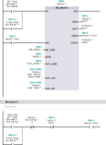
Here's one that I have running on a system that's networked to 40+ devices. I have an FB that sequences through reading and writing to each address as needed with multiple data addresses, instrument addresses and modes.

The reason for the second network is to allow the program a scan cycle to change all those values in the master. So it activates EN, then REQ on the next scan. Probably not relevant here but I also put in a reset timer in case there's an issue with one instrument, so it will only slow but not stop the rest of the sequence.

The PTR here is just a single UInt as the data length is fixed to 1 since all the addresses I needed are spaced apart.

Also I've just realised when I've taken the screenshot, I've got the wrong data type on the MB_ADDR. Should be UInt and I have it specified as USInt, luckily implicit conversion had my back there.

Modbus Master TH.png
 

Similar Topics

Hi all, Currently having trouble getting a speed reference to write over modbus to an Omron M1... I can successfully write a run command and...
Replies
6
Views
257
HI i would like to know how to get a variable that will store the amount of times a program has been executed. The issue is I have 3 DBs for 1 FB...
Replies
2
Views
82
Hi, I have attached herewith one image which our programmer has been used in S7 1500 PLC. Now we need to use the same instructions in S7 1200 PLC...
Replies
4
Views
120
commentaire communiqué siemens s7-1200 avec vfd delta ? (cablage et sur tia portal )
Replies
0
Views
139
Hi, I have a 1214 on ip 192.168.0.100. This is connected to other modules through a switch on same network. I need to connect this to a company...
Replies
1
Views
183
Back
Top Bottom