Safety Precaution for heated acid tanks question

ceilingwalker

Lifetime Supporting Member
Join Date
Mar 2010
Location
Phoenix, AZ
Posts
1,586
Good day all. I have a dip-tank that contains acid and this tank is heated by a 12000watt heater. The way the control was wired was: when SP is less than PV, SLC500 Relay Output Module sends 120 VAC to a one-shot fuse (thermal fuse) and then returns to the control cabinet where it energizes a relay coil that pulls-in contacts, closing the 3-phase power, energizing the 3-phase heater. I had two objectives: 1. Remove the more dangerous 120 VAC in the operator’s path and use a lower 24 VDC circuit and 2. Create a more specific alarm for the one-shot fuse to aide maintenance techs while troubleshooting. I accomplished this by adding a DC-Sink input module and put 24VDC to the one-shot fuse and then connected the coil for the heater relay directly to the SLC500 Relay Output Module. Now this circuit works like this: 24 volts goes across the thermal one-shot fuse and lands on the DC-Sink module. As long as the processor sees a “1” in the bit box for that one-shot, and if the SP is less than the PV, the Output Module will energize the coil, pulling-in contacts and provide 3-phase power to heaters.
Here is my question: Can anyone think of a reason why would NOT be a good idea? I believe I have considered every possible safety precaution and have determined that the system will be just as safe however, I would like to hear what you experienced folks have to say. A second, third, fourth, etc…. pair of eyes on this will make me more comfortable with this change. Thank you
 
Now this circuit works like this: 24 volts goes across the thermal one-shot fuse and lands on the DC-Sink module. As long as the processor sees a “1” in the bit box for that one-shot, and if the SP is less than the PV, the Output Module will energize the coil, pulling-in contacts and provide 3-phase power to heaters.
Is the heater control circuit tied in with any safety relays for the tank, such as an access hatch or manway? Maybe there is no access- ever!
 
Is the heater control circuit tied in with any safety relays for the tank, such as an access hatch or manway? Maybe there is no access- ever!
Operator has ability to turn on/off via HMI. Also, if the level goes low, there are instructions in the program that will not allow heater to energize. Is this what you were asking?
 
No, that was not the issue I was asking about. Does this acid tank have a hatch for cleaning or inspection or repairs? If so, and entry would be hazardous to personnel (probably would depending on strength of acid), then how is the entry way protected to prevent unauthorized access? Does it have a safety lockout relay, and is that safety relay tied to your heater to prevent it going on during tank access?

That is all I was aksing.
 
You need a safety assesment of the equipment both to CYA in case something happens and to help with you design. What happens if it overheats? Do things go boom? Can someone get hurt?

In most plc heating systems you want a redundant safey. Most modern heater cicuits use SSR to control the heater power Vs using a mechnaical contactor as mechanical contactors have reduced life in this arena. most systems have a mechanical contactor above the SSR that will cut heater power based to several factors.This mechanical contactor is best to be a forced guided safety contactor in my above code / design opinion but go by your risk assesment.

There are normally at least 2 thermal indicators also. 1 for control(PLC in your case) and 1 for Safety / Limit. If the control probe (RTD /TC) fails the limit probe should shut the system off on overheat via the control output (Via the SSR and Mechanical contactor). You should also kill the output from your plc if the PV is over / under a certain range (Think open or grounded TC)
 
Last edited:
You need a safety assesment of the equipment both to CYA in case something happens and to help with you design. What happens if it overheats? Do things go boom? Can someone get hurt?

In most plc heating systems you want a redundant safey. Most modern heater cicuits use SSR to control the heater power Vs using a mechnaical contactor as mechanical contactors have reduced life in this arena. most systems have a mechanical contactor above the SSR that will cut heater power based to several factors.This mechanical contactor is best to be a forced guided safety contactor in my above code / design opinion but go by your risk assesment.

There are normally at least 2 thermal indicators also. 1 for control(PLC in your case) and 1 for Safety / Limit. If the control probe (RTD /TC) fails the limit probe should shut the system off on overheat via the control output (Via the SSR and Mechanical contactor). You should also kill the output from your plc if the PV is over / under a certain range (Think open or grounded TC)

Yes, all the redundancy is already in place. RTD fails-high, have level sensors that will turn-off sparger pumps and heat when low, heat is disabled when sparger pump is not operating, and over temp will also disable heaters. Only thing changed was feeding one-shot input to module as opposed to going to the relay coil.
 
As I read it. Before, you had a PLC controlling the system and the overheat stat went through a relay. You would need two points of failure to get a dangerous condition. Your new system just has a PLC controlling it, by the PV value and by controlling the overheat relay. If that is the case then you have lost diversity, if the PLC fails then the system could overheat.
 
Put a hardwired thermostat like a danfoss direct on the heater, when this is in alarm switch off the power to the relais. overruling any electronics. same is done in the simple frying pan at home, they use two thermostats.
 
Put a hardwired thermostat like a danfoss direct on the heater, when this is in alarm switch off the power to the relais. overruling any electronics. same is done in the simple frying pan at home, they use two thermostats.

These one-shot's are part of the heater. When the hot zone exceeds its temp limit, it opens. When that opens, the logic will change to a "0" and the relay output will also go to "0", disabling the heater.
 
As I read it. Before, you had a PLC controlling the system and the overheat stat went through a relay. You would need two points of failure to get a dangerous condition. Your new system just has a PLC controlling it, by the PV value and by controlling the overheat relay. If that is the case then you have lost diversity, if the PLC fails then the system could overheat.

It has always been controled by the PLC, only using the SP vs. PV, over temp logic, etc... . The difference is the output no longer goes across the one-shots and then back to the relay coil. Instead of one circuit, I have created two. This way we no longer have the 120 volt in the operators' path, only 24 volts. Then the output, provided all of the permissives (safety interlocks) have been met, will energize the coil directly from the output module.
 
What do you mean by remove the 120 VAC from the operators path? It should be in the control cabinet where a operator never should be?

If it's in the control cabinet why does it matter if their is 3 phase in their also it's defeating the purpose?

24 volts is good in enclosures that have just 24 volts and good to do new controls in 24 volts but newer installs try to keep 24 volt controls in a separate cabinet from 3 phase as the controls are accessed more often.

The whole reason for using 24 volts is arc flash.Voltage below 50 volts RMS does not have the potential to create a serious arc flash / blast but the 3 phase in the same cabinet does.

Just food for thought.
 
It seems to me that the original designer was concerned about possible PLC failure and so he / she put the thermal fuse between the PLC and the Relay. You are now routing the thermal fuse via the PLC input which negates the original design logic. So I agree generally with BryanG. In that case you would be better off driving a 24 Volt relay from a PLC relay output with the thermal fuse in series with the coil as before which would achieve what you want to do and still maintain the original design intent.
 
Last edited:
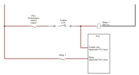
I sketched up a drawing of my suggested circuit and I think Calistodwt. It gives the diagnostics you were looking for without loosing the diversity. It adds diagnostics for the relay operation, if you have a spare contact on the relay.

Circuit Maintaining Diversity.jpg
 
What do you mean by remove the 120 VAC from the operators path? .

It used to be wired that the output (120VAC) would come from the output module, go across the one-shot fuses at the tank- heater, then back to the control cabinet and to the relay for 3-phase power to the heater leads.
 
It seems to me that the original designer was concerned about possible PLC failure .

Exactly! This is why I was asking for input about what I had done. If the PLC fails (in theory) there should be no way the heater would energize, there are too many conditions that wouldn't be met to permit it.
 

Similar Topics

After some interesting conversation regarding the safety of emergency stops, I saw some posts talking about the safety standard conversation...
Replies
24
Views
608
Hi, I am using AB 5069-L306ERS2 CPU. My system should achieve SIL-2. I have safety door switches connected to AB 5069-IB8S module, and I want to...
Replies
1
Views
110
I'm struggling to get an FR-E800SCE to work on CC-Link IE TSN. I'm sure the issue is with the drive, when I plug in the network cable I get no...
Replies
1
Views
105
Hi I have a yaskawa gp7 robot arm which I am going to use for machine tending with a cnc mill. Is it a good idea to buy a SICK laser scanner for...
Replies
5
Views
240
Power flex 527 Network based safety drive had faulty and alarm pop up SOS Code internal fault Unable to set or clear the fault manually or...
Replies
5
Views
116
Back
Top Bottom