Series Resistor Circuit Voltage (2 Power Sources)

I like to use Kirchhoff's current law and Kirchhoff's voltage law.

KCL: the sum of currents flowing into a point in the circuit must be equal to zero.

KVL: The sum of voltage changes in a loop must be equal to zero.

As there are no break-away points, KCL is easy. There is one current, and we will call it 'i' and we will assume it is the current flowing in a clockwise manner.

if you then start at any point in the loop and add up all the voltage changes you get (in my case starting in the lower left hand corner and moving in a clockwise manner).
9 - (47k * i) - (27k * i) - (56k * i) - (20k * i) - 12 = 0

and if we stopped half way with voltage summation:
9 - (47k * i) - (27k * i) = Vb

You now have two equations with two variables, which can be solved for Vb and i. Of note, i is a negative number as current is flowing anticlockwise in this case, not clockwise like in my definition.

Thank you
 
That's a nifty little setup. How are the patterns controlled?

Follow this Youtube series, links to the Arduino code are in the comments.

The "patterns" are mostly created as for/next loops within the code.

Many people are amazed that only 4 connections to the Arduino are needed to control 8x8x8, that's 512 3-colour, so that's 1,536 LEDs in total.

I've modified/optimised/streamlined/corrected some of the code, but the code published works ok.

Very interesting, I'll definitely check it out... thank you.
 
It would be nice to see some student out there with access to a bread board and hardware to actually put this together and measure it. Eliminate all doubt.

Now we're asking students to help us out? What has this site come to?!? :)

Actually, I probably have everything that I need in my car (I call it the "Rolling Room of Requirement", where I have one of everything, and two of most things...).
 
Actually, I probably have everything that I need in my car (I call it the "Rolling Room of Requirement", where I have one of everything, and two of most things...).
__________________

Then please humor us.

The posted software is just doing the math as others have done. But nothing like the real world.
 
Then please humor us.

The posted software is just doing the math as others have done. But nothing like the real world.

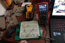
Okay, but I cheated on the voltage a little. My Rhino needs new batteries...

6.85 volts instead of 12, and 4.67 volts instead of 9.

At the measurement point I read 5.76 volts.

The measured resistance was 149.3K, close enough for the girls I go with...

150K the hard way.jpg
 
Okay, but I cheated on the voltage a little. My Rhino needs new batteries...

6.85 volts instead of 12, and 4.67 volts instead of 9.

At the measurement point I read 5.76 volts.

The measured resistance was 149.3K, close enough for the girls I go with...

Ok great. Because I am lazy, without going through the math using your voltage differences and the tolerances of your resistance does it match the software?
 
Amazing

With all the 'how do I connect this widget to my xxx PLC', and 'what is wrong with this spiffy newfangled software', a post on a (relatively) simple subject gets over fifteen hundred views in a little under a month!
 
Ok great. Because I am lazy, without going through the math using your voltage differences and the tolerances of your resistance does it match the software?

Oddly enough, I feel a bout of laziness coming on too. :)

I would say that the circuit analysis software is pretty darn close.
 
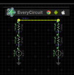
Capture.PNG
 
I used EveryCircuit on the OP's original voltages, and got this... not sure why it has rounded some voltages to 1 decimal place (the one I wanted to show !!) and others to 2, but 10.5 is close to my calculated 10.48, so I believe my calculations are better than some posting on this thread....

2016-12-04_230749.jpg
 
Last edited:
Here's an excel sheet I quickly put together, only the yellow cells contain values I entered, the rest are calculated...

2016-12-04_235344.jpg
 

Similar Topics

how to communicate FactoryTalk Optix and Mitsubishi Q Series. I want to know the details of that
Replies
0
Views
37
I cannot add SLC500 analog input tag (I: 8.3) to EZSeries Touch Panel Editor (V 5.3). I used all the listed tag datatype but it all says "Invalid...
Replies
10
Views
259
Hi, We couldn’t find anything specific, so am starting a new thread. I’m trying to migrate a config from a ML1400 to a micro820 & am experiencing...
Replies
1
Views
93
Does anyone know what the data transfer rate for this series of CompactLogix PLC's? 1769-L24ER-QB1B to be exact. Cheers.
Replies
1
Views
98
Back
Top Bottom