
drbitboy
Lifetime Supporting Member

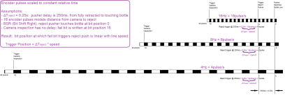
In the attached image, encoder pulses are scaled to constant relative time at three different line speeds: 16Hz; 8Hz; 4Hz; Hz ≡ pulse/s.
Assumptions
This is what @Steve Bailey said in Post #2.
* Adding an inspection delay, e.g. ΔTinspect = 25ms between camera inspection trigger at bit position 16 and fail signal received by PLC, when failed bottle is "at" a downstream bit position, simply adds that delay to the Trigger Position calculation:
Assumptions
- BSR (Bit Shift Right); reject pusher touches bottle at bit position 0
- 16 encoder pulses model distance from camera to reject
- PLC inserts fail bit at bit position 16
- ΔTreject = 0.25s: pusher delay is 250ms and constant for all, i.e. independent of, line speeds
- from PLC writing the output bit to command fully retracted pusher to extend, to pusher (or air) touching bottle
- PLC needs to issue reject trigger signal 0.25sbefore fail bit reaches bit position 0
- i.e. before modeled reject bottle reaches modeled reject pusher
- Camera inspection has no delay; fail bit is written at bit position 16 i.e. at camera position*
- Fail bit position at which PLC issues reject trigger is linear with line speed:
Trigger Position = ΔTreject * speed
This is what @Steve Bailey said in Post #2.
* Adding an inspection delay, e.g. ΔTinspect = 25ms between camera inspection trigger at bit position 16 and fail signal received by PLC, when failed bottle is "at" a downstream bit position, simply adds that delay to the Trigger Position calculation:
Trigger Position = (ΔTinspect + ΔTreject) * speed
Attachments
Last edited:


")
