Siemens S7-1200 - ifm IO link

Pablox

Member
Join Date
Oct 2010
Location
Home
Posts
72
Not too familiar with Siemens plc's and never used IO link before , but got an ifm starter kit, so some dumb questions coming up. I am good on relay logic, but bits n bytes are a bit of a struggle for me.šŸ™ƒ

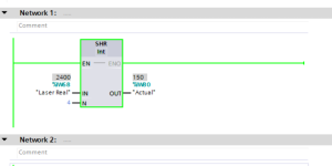
I have the S7 set up with the IO link master. It has a O5D150 laser sensor, connected on Port 1 and all good so far, all working and I have a " Raw data value, and using a shift register , I have a real value of 150 cm in my Tia Portal on %IW80 (y)

I then acquired a E30391 ifm display unit set the master port as "IO link In/Out 16/16 byte and connected it to Port 3 on the ifm master and disabled the two ports not in use. It supplied the Q address as 64 -79. All seems well, no errors on the program.

I uploaded here the "bytes info" from this display unit and my question (got there eventually (y)), is how do I get my real value on %IW80 onto this ifm screen. What blocks do I use and what format is the S7 output.

All the hardware is fine and working, I just need to know how to understand/decipher how the bytes info in the upload translates into Siemens output block.

eg say, I want a one line display with my real data from %IW80 displayed on a green colour with led 2 on.

I will try to work backwards to see if I can figure it out.

Ifm e30391.jpg
 
Create a couple of tags for the LEDs and LAYOUT, LEDS=%QB76, LAYOUT=%QB77 and write a value of 4 to the LEDS tag using a move instruction. If LED2 comes on then you have the correct byte order in the plc compared to the IFM unit, if the LED does not come on, swap the addresses for the LEDS and LAYOUT.
 
I'd recommend making a PLC Data Type for that whole output structure. Call it IFM_HMI_Type or whatever. Then you can create an output tag for Q64.0 of type IFM_HMI_Type, and it'll apply the whole structure, so you grab whatever tag makes sense.


You'll probably need to do a little testing to show which byte in their picture (left or right) is the upper/lower byte of the word. Not all devices use the same order that Siemens does.
 
Create a couple of tags for the LEDs and LAYOUT, LEDS=%QB76, LAYOUT=%QB77 and write a value of 4 to the LEDS tag using a move instruction. If LED2 comes on then you have the correct byte order in the plc compared to the IFM unit, if the LED does not come on, swap the addresses for the LEDS and LAYOUT.

Yes, thanks a lot m8, Led 2 came on (y)
I still don't know how you got the 76 and the 4, but I will do some experimenting.


I think I got there, the addressing starts at 64, so 76 is the led byte and 4 is the bit


.
 
Last edited:
I'd recommend making a PLC Data Type for that whole output structure. Call it IFM_HMI_Type or whatever. Then you can create an output tag for Q64.0 of type IFM_HMI_Type, and it'll apply the whole structure, so you grab whatever tag makes sense.


You'll probably need to do a little testing to show which byte in their picture (left or right) is the upper/lower byte of the word. Not all devices use the same order that Siemens does.

Sounds good, but I don't know how, but making progress albeit it slowly. :)

I have only really used smart relays like the Siemens Logo and the Schneider Zelio prior to this, so bit of a learning curve with this bits n bytes, words and ints etc.


.
 
Last edited:
Are you writing to an input there? I didn't even know it would allow you to set it up that way as it could cause a conflict if you assigned an actual input to that address.

Judging by that bit map, if you replaced IW80 with QW64 on your SHR block then it should simply write your value straight to the output.

I think I had some long forgotten plan, about using the actual distance as an alarm input i.e IW80.
As you said, replacing IW80 with QW64 sounds logical, but thanks to the posters above, I just moved IW80 to IW64 and my display worked perfectly and I used the ifm "Moneo" software to change displayed units and descriptions on the display.

I actually bought the wrong ifm display, I intended buying the one that connects directly to the io master and picks up the process values without programming.

But all ends well, all working and thanks to the posters, I learned a bit, if you pardon the pun. :D
 
Another problem.
I have one of the ports on the io-link master configured as "digital input+pqi". Tia sets an "I" address of "2".

In the Tia program, I am tagging this input as %I2.0.
I am shorting brown + white wires on the io link cable and getting a DI indicator on the io master, but the %I2 contact in the Tia program is not changing state.

Am I tagging it correctly
 

Similar Topics

Hi all, Currently having trouble getting a speed reference to write over modbus to an Omron M1... I can successfully write a run command and...
Replies
6
Views
256
commentaire communiquƩ siemens s7-1200 avec vfd delta ? (cablage et sur tia portal )
Replies
0
Views
137
Hi, I have a 1214 on ip 192.168.0.100. This is connected to other modules through a switch on same network. I need to connect this to a company...
Replies
1
Views
183
Hi Experts, I would like to make firmware upgrade from v3.0 to v4.5 (S7-1200 CPU 1215C). Can I do it from v3.0 to v4.5? Do I need to take some...
Replies
6
Views
294
Hi Guys, I am trying to establish communication over profinet between Siemens S7-1200 PLC as IO device and codesys plc as IO controller. But I am...
Replies
43
Views
2,880
Back
Top Bottom