Simple reset timer program?

i've just given this a go in RSEmulate and it seems to work (but whether it's good programming practice, we'll have to wait and see who shouts at me :p )

check out the MVM instruction - Masked Move (under move / logical tab).

I set up the Source to be I:0.0 - my digital inputs.

I set the mask to be 0000000000001111 (binary)

I set the Destination to be N7:0

this assumes your four inputs are starting at I:0.0 and are sequential, i.e. I:0.0, I:0.1, I:0.2 etc. If you only want 3 inputs, then change the mask to be only three 1's on the end.

Basically what this instruction does is look at the word starting at I:0.0 and copies 16 bits (1 word) to the memory location specified in the destination. The trick is, that it applies a mask to the source data. If the bit in the mask is a 1, then whatever the corresponding bit in the source is will be copied as it was. if the mask is a 0, then the destination will be a zero no matter what the source was.

Now go look at N7:0 in your data table. Make sure your radix is decimal. Put input 1 and 3 on, and you'll see 5. Put 1 and 2 on, you'll see 3.

This of course only works if the inputs you're using are sequential.

You could now do some maths on the memory location at N7:0, i.e. compares etc.

hope that's not too complicated, but in my head its a simple one rung instruction that gets you an integer to play with from as many binary inputs as you like.

Can send you a .RSS file if you need, just don't have RSlogix on this machine.

Steve
 
Saffa, you are incorrect when you said "if the mask is a 0, then the destination will be a zero no matter what the source was". The mask specifies which bits to modify in the destination (where there is a 1), but leaves destination bits unchanged where the mask bit is a 0.

So, Alan's solution will work, but can suffer a problem if any of the unused bits in N7:0 get turned on by mistake (!?!).

If you add a rung in front of the MVM with a CLR N7:0, it will work fine, and be "fiddle-proof". Or you could just use an AND instruction instead of the MVM, specify source B as 000FH (it will display as 15), and unused bits in the destination will be zeroed.
 
Last edited:
Now how the heck do I make sense of all these different inputs to change my timer? AH?!
Here is one way that has worked before (that could be easier for you to understand). I am assuming that you will have 3 Inputs available to use. You can expand those 3 to 7 internal "inputs" B3/1 to B3/7, and use the B3 bits in place of where you would normally use I bits. See PDF file below.

For example, when the new B3/1 "INPUT ONE" is ON, you could MOVE a certain time value into the Preset Value of your Countdown Delay timer (previously your "5-minute Delay" timer. You could now have 7 different time values that would be auto-loaded to this timer, depending on the 3 input switch settings. If you want the switch to be easy to use and to switch in numerical order, then you would need to buy a BCD thumbwheel switch (instead of using ordinary on/off switches). You can buy thumbwheel switches with any number of output digits from 1 to 10, so getting one with a 3 digit output should be no problem. Notice that I did not use the "0" input, assuming that if all switches are off, then no time has been set. Howver, you could possibly use 0 if you do not need an OFF time setting. Note that LogixPro does not have a 1.0 time base, so set T4:1 to have a 1.0 second time base.
 
Last edited:
The mask specifies which bits to modify in the destination (where there is a 1), but leaves destination bits unchanged where the mask bit is a 0.

Yes you're right, got myself a little confused with the MWM - don't use it much. An AND instruction would behave as I had described, but not the MWM. Cheers for pointing that out.
 
Thank you all so much. It makes since. Now I will go order a (few) BCD thumbwheel and start writing the final program. I will post it afterwards so it can be checked for errors by you pros. Thank you all again! (y)

Joe.
 
To test your program you could use another N7 word instead of the inputs and manually enter values from 0 to 15, and check that the program works as you want it and then when you get the thumbwheel switches it just a matter of connecting them to your PLC and changing the N7 word in your program back to the input word.
 
Thank you all so much. It makes since. Now I will go order a (few) BCD thumbwheel and start writing the final program. I will post it afterwards so it can be checked for errors by you pros. Thank you all again! (y)

Joe.

You said "a (few) BCD thumbwheels" - are you going to have more than 1 digit? eg. 00 to 99

If you are going more than 1 digit, then the data coming into you inputs will be BCD coded, not binary, and will need converting with the FRD (From BCD) instruction.

This takes the BCD bit pattern (eg. 1001 0011 = 147), and converts it to the correct value, 93

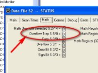
And that is where you may have a problem. The SLC range of PLCs has an "Overflow Trap" bit in the status file. As you move the thumbwheel between numbers, they very often give illegal non-BCD codes as the wipers travel over the pcb inside the switch - eg. 1101 is not a valid BCD number 0-9.

Overflow is considered a Minor Fault until the program ends, then it will be "promoted" to a Major Fault, so if the "Overflow Trap" is set at the end of the program scan, then the PLC will Major Fault.

You must put an OTU of the trap bit after any math instruction that could cause overflow, although to save doing this loads of times, it is quite common to put an OTU of the overflow trap bit S:5/0 as the last rung of the program to prevent it major faulting.

2012-03-16_125804.jpg
 
To test your program you could use another N7 word instead of the inputs and manually enter values from 0 to 15,...
You said "a (few) BCD thumbwheels" - are you going to have more than 1 digit? eg. 00 to 99.
I only have 6 inputs and need 3 for the flush system, or I could get by with just 2 on the flush, but would rather not.
Guys, some of you are not listening to Joe the "Customer". If I remember, he plainly stated that he would have only 6 inputs but 3 would be used for other things, leaving ONLY 3 that can be used for the time-setting input. Forget 0-to-15, forget 00 to 99. Instead. think about 000 to 111 binary (0 to 7 decimal).

Joe needs a thumbwheel switch with 3 binary-position output terminals, but only a 1-decimal-digit input wheel (0 to 7, or the more common 0-to-9). Digikey has versions that have a either Binary-Coded-Decimal output terminals, or decimal-number outputs.

http://parts.digikey.com/1/parts/980079-switch-thumbwheel-black-frnt-mnt-a7as-206-pm-1.html

I googled the term [seal-in] and it is similar or actually synonymous with the latching relay...
Joe, No it is NOT synonymous with a latching relay. Please do not use a latching relay for this function.

Also you mentioned needing 3 inputs for the flush system, but earlier you said you had a Trigger and a Reset. What is the other input?
 
Last edited:

Similar Topics

So i am a EE and mostly work in protections. I recently got thrust into more of a controls roll and need to start learning some logic. What...
Replies
18
Views
6,356
Hi to all, Please find attached a simple CFC circuit of running lights. The problem is that i cannot loop it and make the timer restart again...
Replies
4
Views
3,234
Hello again..trying something on an existing poorly written program and just wanted to double check something system is an A-B MicroLogix 1200 In...
Replies
5
Views
175
Hi all, Writng a FB in ST on Beckhoff TC for a pulser which turns on and off on a cycle, is paused by turning bControlInput to FALSE, but resumes...
Replies
6
Views
265
I'm trying to build my Classic Step 7 programming skills this weekend. I get stuck on little things that are not covered in YouTube tutorials. I'm...
Replies
7
Views
321
Back
Top Bottom