Slc500 Jmp Inst Problem,need Review And Help

av8r

Member
Join Date
Oct 2004
Posts
8
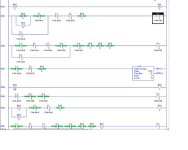
I am having a problem getting the jmp and lbl logic to work in my program. I have attatched a copy of the program and would appreciate it if someone or all could take a look at it and offer some help. I have been looking at this forum for a while now and you guys are definately the best.
A brief descrition of the problem:
This machine has the option of spinning a basket either forward only or forward and then reverse depending on input I1:3. I have put in another switch to allow it to spin 4 ways succesively, fwd,rev,fwd,rev but only one time per scan when the switch is on.
I tried putting the jmp inst after the line which contains t4:dn and then labeling the line which has the external timer 0:2/5. It winds up in a loop and faults. I worked on this for 4 hours on friday and decided to ask the experts. Thanks in advance for reading this and trying to help.
 
Huh?

av8r,
Rube's right. We'll need instruction and rung comments - without we don't have a clue as to inputs, outputs, ect.
Also, I saw no jump or label instructions in your 28 lines of logic
I tried putting the jmp inst after the line which contains t4:dn
T4:?/DN - which one?

You're going have to help us help you...

Mike
 
If i understand correctly, you are jumping backwars in your program. The watchdog is probably timin gout causing your fault. Do you have your JMP and LBL swapped? We can't tell what you are trying to do with the JMP/LBL by your post.

The attachment is the rungs av8r is talking about for those without RSLogix500:

jmp_lbl.jpg
 
Derek's post was the inspiration that sparked this insight.

I think you may be making one of the classic mistakes made by newcomers to ladder logic. You're assuming that the PLC program needs to pause while a step of your sequence executes, so you program a loop. Don't do it.

If you can't think of a way to program machinery sequences in ladder logic without using loops, you're not thinking hard enough.

I'm not trying to say there is no place for Jump/Label combinations in ladder logic. I'm just saying that for straighforward sequential control, they're the wrong tool for the job. The machinery may pause while the step is executed, but the program doesn't
 
Greetings av8r,

I fully concur with everything posted by my distinguished colleagues ... here are just a few “while we’re at it” type observations of my own ...

all of your timers have presets of either “1” or “2” or “3” ... yet the time bases are all set for “1” ... most programmers would tend to use the “0.01” time base and adjusting the presets accordingly ... theoretically this will give your timing functions better resolution ... note: this does NOT have anything to do with your specific problem ... I just thought I’d mention it from a “programming style” viewpoint ... I'll admit it's a "picky" point ...

more important ... you have the output O:2/6 driven by two OTE instructions ... once in rung #12 and then again in rung #16 ... this is often called a “double coil” arrangement ... you can research the forum for any number of posts on this particular programming “faux pas” ... basically it all boils down to this: whatever you expected to accomplish by controlling O:2/6 in rung #12 will NOT work as planned ... in simplest terms, the OTE in rung #16 gets the last vote for O:2/6’s OFF or ON status during each processor scan ... specifically, the output O:2/6 will be controlled ONLY by the logic in rung #16 ...

then from the “what the heck is this all about?” department ... regarding your rung #13 ... I’ve never seen anybody (outside of a lab experiment) do that “unlatch” thing to the counter’s “CU” bit ... basically this logic turns C5:0 into a “scan counter” ... specifically, whenever I:1/11 and I:1/7 are both true, then the counter will increment by “1” each time the processor scans the program ... in simple terms, it will “run like a striped ape” as the saying goes ... once the counter reaches its maximum value of 32,767 then it “rolls over” to “-32,768” (note the negative sign) and then it continues counting up again from there ... what were you thinking about when you did this? ... I note that you don’t have any other references to C5:0 in your program ... tell us what you WANT to happen and we’ll help you get there ... (wild guess: you were playing around with the JMP and LBL instructions and you temporarily inserted this CTU "scan counter" arrangement as a "test device" ... whenever the counter's accumulator is changing, then this particular rung is being scanned ... if THIS is what you had in mind, just say so ... actually this particular troubleshooting approach is an EXCELLENT idea ... you are to be commended if you came up with it on your own) ...

then in your rung #14 ... you have an “unlatch” command to turn bit B3/16 OFF ... but there is nothing in your program to turn it ON ... what were you thinking here? ...

well, that’s enough for now ... again, please provide some documentation for us to go by ... and give us some specific details about what your program is supposed to do ... we’ll do our best to help ... but I’m afraid that we’re not going to be able to give you anything much more specific than what you’ve already been given until we have some more information to work with ...

and welcome to the forum ...
 
Questions from Ron

Ron,
I was trying to get this to work by utilizing the jmp/lbl. I have cleaned up the program and done away with the remnants of this tryout.
With regards to your comment about the output O:2/6 not working as thought. It does. What this does is turn the vfd to the run state while also turning on an multi-function internal switch. The multi function switch frequency takes precedence over the aster frequency so i can get a slow speed out of the drive while the bucket is in the coating.

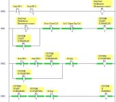
I put labels on the ladder for you guys to look at. The machine function is as follows.

1. Operator presses 2 buttons PB1 and PB2
2. The bucket with the coating moves up propelled by a double cylinder.
3. The basket spins fwd at low speed for the amount of time set by an external timer 1
4. The bucket moves down 1 cylinder length and the basket spins either fwd only or fwd and the reverse. This is set by an external switch. This is where i want to be able to spin again fwd then reverse if a switch is closed.
5. The spin cycle completes when tmr 1 times out
6. The bucket moves to the lowest position and the cycle is complete.

I hope this helps everyone who has taken the time to review my problem

Thanks in advance.

AV8R

The cleaned up program is attatched.
 
Greetings av8r,

sorry that I don’t have time to dig into this right now ... but I’ll at least offer this much ...

you said:

With regards to your comment about the output O:2/6 not working as thought. It does.

well ... I don’t want to argue with you ... but ... I’ll make a friendly $5.00 wager that if you were to totally remove the branch from your rung #12 (the one containing the first OTE for O:2/6), that the program would continue to operate EXACTLY the same AFTER the deletion as it did BEFORE ...

specifically, the first OTE for O:2/6 (located in rung #12) is being “overwritten” later in each scan by the second OTE for O:2/6 (located in rung #14) ... in simple terms, the branch located in rung #12 might just as well be lying out in the parking lot for all the good that it’s doing you ... sorry, but that’s just the way this ladder logic thing works ...

anyway ... the other guys here will probably have everything figured out before I get a chance to work on this again ... but maybe I’ll have time to work on this some more tomorrow ...

thanks for the improved documentation ... and I hope that all of this works out for you ... by the way, what’s your deadline on this project? ... and “As Soon As Possible” is not a valid answer ...
 
Comments:

Things I'm noticing as I go through the code (first pass impressions):

Rung 0 & 1: Rung 0 does nothing, as it's function is duplicated on rung 1, and the bit (B3/0) is not used anywhere else.

Rung 1 & 2: The Door Close Limit Sw, and the Sol 1 safeties aren't safe. They only prevent the machine from being started, not operatoed in an unsafe manner. Hopefully that's what you intended.

Rung 2 & 3: The point of rung 2 confuses me. I see you don't want to do the actual starting (B3/3) until two start PBs are released. But if the operator is pressing the one START PB with one hand, the other START PB with the other, how llkely is it that he will press the E-Stop with his third hand? Nothing wrong, just weird.

Rung 4: B3/1 is on only when the START buttons are pressed. B3/3 won't fire unless the START buttons are released. The only way both of these statements can both be true is if the operator presses both, releases both, and then holds them both down for the remainder of the Run. Is this what you intend? Otherwise, B3/4 can be considered non-functional.

Rung 5: I'll have to come back to this, once I understand what you intend for the functionality of B3/10 and B3/12. Annotating these bits would be good. Annotating all of the B3 bits would be very good.

Rung 26 (to find out about B3/12) & 22. I'm guessing that B3/12 represents the "END" step of your sequence. It looks like B3/10 has somehow been set in you logic (due to a previous run). But it won't drop out until the system is "Running" (B3/4), which will drop out B3/10, trigger B3/12, and then next scan launch B3/5.

Scanning the rest, I'm not sure how well I can follow the logic without a P&ID, or better annotation on your Outputs and Inputs. For example, if O:2/2, Sol 1 Upper Dip Cyl is energized, does I:1/8 In Dip Position get made, unmade, or what?

Without annotation on all your B3 bits, I have no idea even what you are TRYING to accomplish.

Hopefully you can fix what I've pointed out here. The biggest stuck point that I see is with your B3/1 on rung 1. Delete the two PB contacts and it just might work.

Back to the drawing board.


EDIT

Thanks, Ron. I hadn't even gotten far enough to notice the double coil.

You are, of course, correct. None of the logic for O:2/6 on rung 12 is valid, because it's overwritten by the logic on Rung 14.

He might have gotten confuesd by not listening carefully enough. You said "O:2/6 in rung #12 will NOT work as planned". He seems to have heard was O:2/6 will NOT work." Hence his reply "this does is turn the vfd to the run state".

I wonder what he'll make of my critique.
 
Last edited:
Reply to Ron

Ron,
I had to disconnect the machine and move it today so i wont be able to try what you suggested but i will. Maybe i just got lucky. If there is another way that would be better please give me your thoughts.
Of course everything is ASAP, but in reality i need to get this done by the end of this week. The machine is scheduled to go into a commisioning stage next week.
Thanks for the follow-up.

AV8R
 
Reply to Allen

Allen,
I am not the original author of this logic so i am trying to figure it our as i go along.
I agree with some of the points you made and when i hook up the machine tommorrow i wil try and make a little more documentation available.
Thanks in advance for your comments.
AV8R
 
Replies

Ron,
I completely deleted rung 12 , and i owe you 5.00. Hopefully a thank you will suffice. After staring at the logic for a while we sometimes do illogical things.

Allen,
Per your comments:
Rung 0 Deleted. I never saw that
Rung 1&2 you are correct in your assumption.
Rung 2&3 I see your point. I didn't write the logic so i dont know what the reasoning was behind it.
Rung 4 B3/1 I see the same thing.
Rung 5 I can't explain B3/10 or B3/12 until i fire up the machine this morning.
Rung 26 B3/12 you are correct.

As far as comments go i was taught that if you ask for help be prepared for anything. I welcome comments such as those from you guys.

Thanks again in advance,
Chris Marinello
 
Are you sure?

Rung 0 Deleted.
I/m not sure that was the best move. I think instead, you should delete the duplicate functionality from rung 1 (as shwon) This will then make your safeties safe.

[attachment]

I am not the original author of this logic
For better or worse, it's yours now. You may consider rewriting it from scratch. It's only 26 lines of code, which probably don't work anyway. How would you redo it if you were to?

i hook up the machine tommorrow i wil try and make a little more documentation available
One suggestion on annotation. Try to include verbs in describing your inputs and coils (complete sentences are good).

That way, when you look at a contact, it becaomes easy to interpret what's going on.

For example, you have
I:1/7 == Door Up L/S

But since I can't tell if the limit switch is wired NO or NC, I have no idea what
 I:1/7
-|/|-

means. Is the Door Up or Not?

If instead, you were to annotate it
I:1/7 == Door is in the Up Postion (LS-123)

then even without knowing how it is wired, I know that the above code means that the door is NOT in the up position.

plcs.net.jpg
 
It has long been the practice to describe the ture statement of the coils, inputs and outputs. If you want to be more descriptive then that use rung comments.

Door Up NO = Door Up

Door Up NC = Door Up Not (Boolean)

Also use descriptions for alternate positions that are opposites
Door Door
Up Down
LS LS

Door Door
Open Closed
LS LS

Using multiple lines will help keep you rung from wrapping.

What is the name of the motor the VFD is controlling?
Spin Spin
FWD REV
VFD VFD

Chris,

Do you by chance has a printed copy of the ladder logic the shows the other descriptions?


What is Multi-Step, 1 Output O:3/8?
 

Similar Topics

I am trying to convert 5TI program to AB SLC500. But I am not sure the how does jmp instruction work. I try to convert as below. Am I right...
Replies
1
Views
2,284
I cannot add SLC500 analog input tag (I: 8.3) to EZSeries Touch Panel Editor (V 5.3). I used all the listed tag datatype but it all says "Invalid...
Replies
10
Views
259
can the slc500 5/05 send a email and text over Ethernet ?
Replies
3
Views
187
Hello, did anybody know, if there exist an converting cable like the1492-CM1746-M01 (for an 1746-IB16 to an 5069-IB16), for an 1746-HSCE to an...
Replies
3
Views
391
Customer is buying several spare 504 CPU's to have one handy when there's an issue with the ones in operation. Having them on the shelf for years...
Replies
15
Views
2,839
Back
Top Bottom