Split Thermocouple input

wahyu

Member
Join Date
Apr 2023
Location
Indonesia
Posts
7
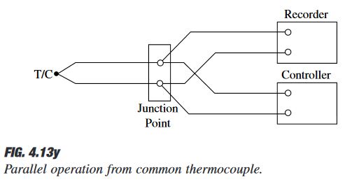
Hello I have a project to record temperature from thermocouple and store it to memory card, the problem is my client didn't provide new thermocouple wiring cable but he want me to make parallel connection with existing thermocouple, so one thermocouple is connected to two device (Yamatake SDC6 temperature controller and mitsubishi Q68TD-G-H01 isolated thermocouple input) when I do that, Q68TD read temperature nicely but Yamateke start fluctuating, does anyone know any device that can split one thermocouple input to two output (Q68 only support thermocouple input/ mV input btw), or any solution. Thank you

sorry for my bad English.
 
I am not aware of thermocouple splitters with TC output. You need either dual TC for measurement or you will need to use analog output(current or voltage) from Q PLC to Yamatake input (current or voltage).
 
1. Burn-out protection

Sometimes burn-out protection circuits interfere with a 2nd device on paralleled T/C connections (although ground loops are also common).

If thermocouple burn-out action is not needed on the 2nd device (because it is not controlling), then you might try turning off the burn-out action on the 2nd instrument to see if that fixes the problem on the Yokogawa. Disabling the burn-out protection will not fix a ground loop problem.


2. Thermocouple Splitter

There is a commercially available thermocouple splitter, the APD 41390.

It is a DIN rail mounted thermocouple splitter, one thermocouple input, two thermocouple outputs, at about $600.

The standard model outputs two thermocouple signals with cold junction compensation (CJC) added to the output, which is probably not what your 2nd device is looking for. The 2nd device is probably looking for the thermocouple gradient signal only, and adding the CJC value to get a reported temperature value.

API informed me in an email that the output CJC can be changed at the factory or in the field (removed a cover and make a change). Removing the CJC on the output would make the output signal mirror or follow the thermocouple gradient signal on the input.

An NIST traceable calibration cert can be purchased, as well.

https://api-usa.com/pdf/api/apd41390.pdf


3. Dual element thermocouple

Replacing the thermocouple with a dual element thermocouple with both elements "ungrounded" might be an alternative. One thermocouple for each instrument, but each T?C measures the same point.

Dual element thermocouple are not very expensive. Installing a dual element T/C would require a 2nd run of extension wire for the 2nd thermocouple.
 
Thanks for the answer maybe I prefer to use the 2nd solution because I can't find way to disable burnout protection at mitsubishi module, btw does connecting thermocouple in parallel really will work with 2 device?, actually I doubted this but my client forced me to try that way
 
One thing you need to think about is for a thermocouple is the voltage produced is very small & the current tiny, so needs a very high input impedence at the controller, this impedence may be different in two different controllers so in effect it is not practical, certainly one RTD input may affect the other especially if the impedence is different.
In general it is a no no.
 
btw does connecting thermocouple in parallel really will work with 2 device?, actually I doubted this but my client forced me to try that way
I disagree that it is a no-no. When I started in instrumentation in 1987, heat treaters were my primary customer base. It was routine to parallel thermocouples for a controller and a recorder. It did not always work, but the test was to try it and see.

Two things can prevent a good reading on both instruments

a. Burn-out protection on one interferes with the other.

b. ground loops from a combination of a grounded thermocouple and the instrument analog input grounds.

Sometimes paralleling a thermocouple works, sometimes it doesn't. The work around was typically dual element thermocouples. The thermocouple splitter is a recent product.

The heavy industries, gas & oil, metal processing mills, mining all use temperature transmitters and temperature transmitters have the same ground loop issue when trying to series connect a 4-20mA signal through two devices. Sometimes it works, sometimes it doesn't. 4-20mA splitters have been around a long time, though.


It is impossible to parallel, jumper or series connect an RTD, because the RTD does not generate its own EMF; the AI's constant current source develops an IR drop across the RTD, which is read by the AI. Any deviant path for the constant current would make the reading unreliable.
 
Last edited:
Keep in mind that if you are going to split the thermocouple like that, you may get inaccurate readings by introducing more junctions that will generate the seebeck voltage the input device is reading. You will need something that is specifically designed for this, and installed exactly how it is prescribed.
 
Keep in mind that if you are going to split the thermocouple like that, you may get inaccurate readings by introducing more junctions that will generate the seebeck voltage the input device is reading. You will need something that is specifically designed for this, and installed exactly how it is prescribed.
Unless the wire is damaged by creating a 'false' junction due to crushing, I disagree entirely.


I saw hundreds or paralleled thermocouple installations that worked just fine when I worked that field. It pays to use thermocouple grade wire rather than extension wire because extension wire is thermocouple wire that doesn't pass the ANSI test for accuracy, but is good enough to use extension wire.


The diagram below is from Bela Liptak’s Instrument Engineer’s Handbook, Volume 1 Process Measurement and Analysis, 4th Edition, 2003. It’s a standard reference for process instrumentation, usually found in company libraries.


Liptak-2003.jpg
 
wahyu, I was going to suggest that if you have available slots in the MELSEC Q backplane, why not adding an analogue output module (such as Q68AD-G), connect the thermocouple to the input module you have (Q68TD-G-H01), copy in the Melsec Q program the input value to the Q68AD-G and connect the Yamatake DCS to Q68AD-G. But this is a very expensive solution. The list price of this output module is well over the equivalent of US$ 1K. I think the solutions suggested above should be far less costly, but just for the record...
 
Due to the cost of trying to use a single channel thermocouple it makes sense just to buy a duplex one, the cost of even a special will be a lot lower than any type of converter or PLC card.
Look at Omega.com
 
Unless the wire is damaged by creating a 'false' junction due to crushing, I disagree entirely.


I saw hundreds or paralleled thermocouple installations that worked just fine when I worked that field. It pays to use thermocouple grade wire rather than extension wire because extension wire is thermocouple wire that doesn't pass the ANSI test for accuracy, but is good enough to use extension wire.


The diagram below is from Bela Liptak’s Instrument Engineer’s Handbook, Volume 1 Process Measurement and Analysis, 4th Edition, 2003. It’s a standard reference for process instrumentation, usually found in company libraries.


Liptak-2003.jpg

You disagree by posting concurring statements? I didn’t say it was impossible, rather that it needs to be done correctly with the correct equipment. Which is what you also said, but in disagreement.

The laws of physics don’t change here. Seebeck voltage will always be present at a wire junction because you cannot guarantee that the probe wire and extension wire are both 100% identical alloys. You’re also introducing the Peltier effect by putting them under a screw terminal. You may not notice these differences, or they may be well within your required margin of accuracy, but they do exist and cannot be discounted just because we personally disagree.
 
wahyu, I was going to suggest that if you have available slots in the MELSEC Q backplane, why not adding an analogue output module (such as Q68AD-G), connect the thermocouple to the input module you have (Q68TD-G-H01), copy in the Melsec Q program the input value to the Q68AD-G and connect the Yamatake DCS to Q68AD-G. But this is a very expensive solution. The list price of this output module is well over the equivalent of US$ 1K. I think the solutions suggested above should be far less costly, but just for the record...

Actually this is a great idea, I have discussed this with my client but cannot realize it because of field condition, the machine run 24hour and only have 8hour break when friday, so that's pretty crucial because that way we have to modify the parameters of yamatake controller in time as short as that (there is 8 yamatake controller on the panel) and also my scope is only on mitsubishi.
but I really appreciate your advice.
 

Similar Topics

hey all, I am struggling with a problem here and out of ideas on how else to achieve the desired result. I have a monitor inside a machine with...
Replies
0
Views
129
Hello everyone. I have an PLC L35 (fmw 16) with address 192.168.1.1 and too many connected ethernet devices (3 hmi, a lot of ethernet port, asi...
Replies
11
Views
747
Basic question: I don't understand why Network 4 is split over two lines. I want it to appear like for Network 3, i.e. all on one line. Does...
Replies
1
Views
750
Hello, I have following control task. I have to limit a current drawn from a source of power in a grid where I have following power consumptions...
Replies
11
Views
1,970
Good morning I have a 1500 CPU with a RS232 card. I receive fom serial card a string like: 123.45 1457.23 456.34 892.34 I need to split the...
Replies
4
Views
4,238
Back
Top Bottom