Start/Stop Moore Machine Help

Nerdlinger

Member
Join Date
Dec 2022
Location
Chicago
Posts
4
Hello Everyone!

It has been a while since I used the method of drawing a state diagram, converting that to Boolean algebra, and translating that to a ladder diagram. I am hoping you can help with my erroneous method!

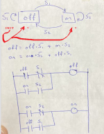
Please see the attached example. I started with a state diagram, with the state options being "on" or "off" and switching between the two via switches "S1" or "S2." I also added the loops where they will remain in their respective state if the switch that transitions the state to the next is NOT true/pressed. (I believe those loops ultimately gets translated to latches.) From there I wrote two algebraic expressions defining the "OFF" state and "ON" state. Finally, I used those expressions to draw the rungs of the ladder diagram. But something is off and here is where I need help:

1. When the program first runs neither "OFF" nor "ON" outputs will be true, so they will never be able to get on! (Look at the first column.)

2. Lets say I program the "OFF" output to have an initial value of "true" upon starting the program. When I hit S1 to turn the machine on the "S1" contact in the 4th rung will close BUT the "OFF" contact right next to it will be open since rung 1 will be broken, even before rung 3 has a chance to latch the "ON" output on!

AH! What am I missing?

P.S. I know this example could be solved with the classic "START/STOP" circuit but I am really trying to remember how to use this method to ultimately arrive at something like the classic "START/STOP." Thank you!
 
First question why ?, it seems a bit ridiculous however, perhaps there is a valid reason or it's just a trial.
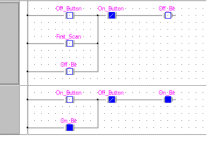
As far as I see it the following does what you want to do in ladder.
The first rung is the off bit, on first scan it latches the off bit.
When the start button is pressed, the stop bit turns off & the start bit turns on.
If you need "OFF" then why not just use the NOT "OFF" bit.

On_Off.png
 
State Machines in Ladder

The PLC class outline at corsairhmi.com has some sections that show a couple of formal ways to do a Moore state machine in ladder. Page 62 introduces the concept of logical feedback. Page 88 talks about state transition diagrams. Pages 165-174 show a method that uses PLC 'relays' to emulate flipflops.

Page 298 has a brief note on Moore versus Mealy. Since all PLC logic is 'clocked' by the scanning nature of the program I contend that you generally cannot do a true Mealy machine. And I doubt that you would want to.

Someone with a specific problem to solve may rightfully say the method shown takes a lot of code (and it does) but an advantage is that it can be reversed to yield the state transition diagram. I've taught it in a college engineering class as it does the same thing that the students learned in their earlier introduction to digital circuits class. I believe that is a part of integrating PLCs into an engineering program instead of just tacking it on as an elective.

I don't use it as much as I used to since SFC appeared but it still has a place. And understanding the theory is so important.

We use an old CD ROM drive turned up on end to act as a garage door opener demonstration. The advantages of doing a garage door opener state machine are that it is very visual with moving parts and the students already have an understanding of how it is supposed to work. It's a challenge to cut and solder into the tiny circuit board traces but it can be done. Usually a series resistor can slow the motor down enough. Use a smaller wattage, make it replaceable, and it may act like a crude fuse.
 
Note that to get a Moore machine the start and stop button inputs need to be image-tabled by the PLC at beginning of scan - which they typically are so you do not need to worry about that.
 
Thank you for the replies! The example I posted above is purely an exercise to get my brain going so I can solve a more-complicated problem. Specifically, I believe the finite state machine diagram and corresponding boolean expression(s) ARE proper. BUT I must be missing something in the translation FROM boolean TO ladder because of what I said in "#2" in the original post. Ultimately the ladder should reduce down to the classic start/stop example. Does anyone see what I am doing wrong? Thank you!
 
Note that to get a Moore machine the start and stop button inputs need to be image-tabled by the PLC at beginning of scan - which they typically are so you do not need to worry about that.

Thank you! Can you please expand on this a bit? The way I understand it is each scan goes left to right, top to bottom so inputs and corresponding outputs will update in that order as well.
 
That is sort of correct, however, inputs & outputs are (well in most PLC's) are updated before the scan & after the scan of the logic.
In most PLC's the physical inputs are mapped i.e. if true or false into internal bits or words (current state) before the scan cycle & the outputs are mapped from the internal bits/words to the physical outputs after the scan of the program logic, the inputs or outputs do not change during the scan of the program.
There are eceptions to this i.e. asyncronous update of the physical I/O to the mapped bits where the state of them can change during program scan.
For example: let's say the operation of a PLC is from going from stop to run the first operation is to update the states of the inputs, the logic is then scanned so from start to end of the cycle those mapped inputs do not change state even if the physical ones do, at the end of the program cycle the physical outputs are then updated with the mapped outputs.
So if an input was true at the start of the program scan then it will remain true until after the scan of the program even if the physical input changed state during the program scan.
The same applies to outputs, if an output is turned on half way through a scan the physical output will not be on until updated at the end of scan.
Internal bits are different, these change state depending on the logic driving them i.e. if the scan time of the PLC is 100ms, an internal bit could be turned on during the scan for example after 10ms into the scan & turned off after 30ms into the scan, if this was an output then it would appear never to be true as these are only updated at the end of the scan.
Hopes that makes sense.
As stated, there are exceptions, some PLC's update the I/O memory map perhaps every 10ms so if the program scan was 100ms then it is possible for the mapped inputs or outputs to change during the program scan, or there are functions that update the I/O mapping for example a function called within the program to update the state of the Inputs or outputs.
 
Thank you! Can you please expand on this a bit? The way I understand it is each scan goes left to right, top to bottom so inputs and corresponding outputs will update in that order as well.

See this link

"Image-tabling" is, I think, the same as the Input Map pattern.

You may be looking for the Step pattern.

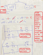
The finite state machine diagram and boolean expressions are correct on paper, but they are also incomplete:

  • Primarily, there is no initialization step (see red in images below), which is one item that @parky's code handles via the First_Scan bit.
  • Secondarily, the finite state machine diagram and the boolean expression assume the evaluation of all logic is more or less simultaneous,
    • while PLC execution of rungs, branches and instructions occurs in discrete, i.e. non-simultaneous, events and in a particular order.
      • For example, say your OFF and ON bitboxes had values of 1 and 0 respectively, with no buttons pressed: the [NO/XIC OFF] AND [NC/XIO S1] would seal-in that 1 value for OFF.
      • However, if the user pressed S1 to try to change the state to ON=1 and OFF=0, then
        • the top branch of the top (OFF) rung would evaluate to False because of [NC/XIO S1],
          • So OFF bitbox would get a value of 0
        • Since the OFF bitbox is now 0 after the top rung executes, the bottom branch of the bottom (ON) rung would not evaluate to True because of [NO/XIC OFF], even though the ANDed instruction [NO/XIC S1] evaluates to True
          • So the ON bitbox would get (keep) a value of 0.
The point is that finite state machines (FSMs) are all well and good, but to program PLCs to model FSMs we need to understand the scan cycle and order of execution. For that you would do well to watch @Ron Beaufort's PLC Bootcamp video series at this link.

The fix to the problem above is simple. Cache the values of the ON and OFF bitboxes to temporary bitboxess ONcached on OFFcached, using the Input Map pattern, at the start of each scan, and use those cached values in place of the ON and OFF bitboxes in the rungs shown (ctually we only need to cache and use the value of the OFF bitbox).

However, even that fix has a problem: on the next scan, which occurs a millisecond or two after the first scan when S1 was pressed, OFFcached bitbox value is 0, but the S1 bitbox is still 1 (unless the operator has very fast fingers). So not only does the bottom branch of the second rung evaluate to False, but so does the top branch of the second rung because of the [NC/XIO S1] with the S1 button still pressed in on this second scan, which prevents that top branch from sealing-in the on bit.
Untitled.png
 
Whoops, ignore this paragraph from my previous post, because I got S1 and S2 confused:
...
However, even that fix has a problem: on the next scan, which occurs a millisecond or two after the first scan when S1 was pressed, OFFcached bitbox value is 0, but the S1 bitbox is still 1 (unless the operator has very fast fingers). So not only does the bottom branch of the second rung evaluate to False, but so does the top branch of the second rung because of the [NC/XIO S1] with the S1 button still pressed in on this second scan, which prevents that top branch from sealing-in the on bit.
...
 
This is perhaps a better approach, similar to @parky's, that yields the desired patterns in ladder. Note that

  • the S2 trigger for the transition to OFF=1 is alone and an absolute that no longer depends on the value of ON; this removes the chicken and egg issue #1 from the OP.
    • So there needs to be an XIO S2 on all other states' rungs.
  • the order of execution has changed, which removes the need to cache the OFF state before the rungs, and fixes issue #2 from the OP.
Untitled.png
 
Thank you for the replies, everyone! You really hit the nail on the head - first, regarding the initial state, first scan bit, etc. whatever you want to call it, I think the state diagram needs to start with a "START" state and a transition arrow going to, say, "OFF" with the "OFF" bit becoming true. So that gets us started. Then, you are correct in that the conversion from boolean to ladder isn't as straight forward as we would like because the boolean expression does not scan like the ladder does. DRBITBOY - your modification seems to work so thank you for that! In an effort to "mechanize" the translation from bool to ladder we have replaced the latching rungs (i.e. the circular arrows in the state diagram) with a pair of SET and RESET coils on the ladder. This ensures we are only in one state at a time, represented by a virtual output in the ladder...so each rung looks like:

|STATE X|-------|INPUT Y| ---------------SET (STATE X+1) ----RESET (STATE X)

Thanks again! Happy New Year!
 
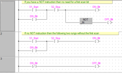
This got me thinking, below is some logic the first rung is if there is a NOT or inverted out instruction so only one ladder rung
The following rungs are as the same without the NOT instruction, no need for first scan.
Yes, I have nothing better to do till tomorrows party time.

On_Off.png
 
Sidebar: my posts simply follow @parky's initial reply in this thread.


This ensures we are only in one state at a time, represented by a virtual output in the ladder...so each rung looks like:

|STATE X|-------|INPUT Y| ---------------SET (STATE X+1) ----RESET (STATE X)

Thanks again! Happy New Year!

:sharp-intake-of-breath-through-clenched-teeth:

There is nobbut wrong with set/reset per se, but for this I would be thinking about how the code behaves across a PLC power loss, as whichever bitbox was 1 would be 1 again after the PLC restart. I looking at that Step pattern from the link provided earlier; the Start/Stop and State Coil/Fault Coil Circuit patterns have the advantage of always coming up in a known state.

It is easy to achieve the equivalent of that
...---SET (STATE X+1) ----RESET (STATE X)
approach without non-set/reset contacts and coils:
...---[NOT STATE X+1]-----(STATE X)---
As long as each ---(STATE X+1)--- rung executes before the previous state's ---(STATE X)---- rung, there will never be two states concurrently with a value of 1 at the end of the program. And that way the PLC program always starts in a known state.

Also, for the START state

  • ...---(STATE Start)--- could be the last rung, driven by a branch of NANDed all other states, plus a seal-in branch
  • ---[NOT STATE Start]--- could be another not-Stop condition added to all other ...---(STATE X)--- Start/Stop Circuit pattern rungs, which makes it easy to return to a known state by SETting the Start bitbox value to 1.
 

Similar Topics

Hello I am trying to make a program work with a sqo instruction .The process has 5 steps ,and a starting step of zero.There should be 8 sec...
Replies
17
Views
1,053
Good morning to everyone on the forum and happy new year. I'm trying to use the following functions in sysmac studio, because I need to enable one...
Replies
1
Views
327
Good Morning , I would like to start a Powerflex 525 with a N.O. Start Pushbutton , and when the N.O. Start Pushbutton is released I would...
Replies
3
Views
1,669
Hello, I am trying to detect when the PLC changes from STOP to START mode. This can be considered an edge case scenario, but I would to analyze...
Replies
4
Views
1,566
Hi all. Having a problem with a PF 525 TermBlk 5 input. I came across the drive the other day and not sure how its running. Both the Enable...
Replies
3
Views
2,143
Back
Top Bottom