the input is not responding fastly 1200 plc

adam_lhadi

Member
Join Date
Feb 2022
Location
algeria
Posts
59
Hi every one

am working on this machine ,where there is a motor that rotates an arm with high speed

when the arm reaches the sensor the motor should break with some mechanism

in the program i used the positive edge detection

the problem is that the positive edge is not always detectable

i set filter to 0.1micr also enable the pulse catch but no good results

also in the hardware circuit i controlled the mechanism coil of breaking with a slim relay

result: sometimes the arm keeps rotating and when he don't he stops but in different places
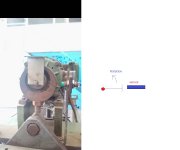
WhatsApp Image 2022-07-21 at 12.24.53 AM.jpeg
 
fix the sensor. if the pulse is too short, make the metal bigger so the pulse will be wider.


We do not know which PLC is in use; if there is a High-Speed Counter (HSC) perhaps the pulse can be detected independently of the scan cycle.
 
Hi every one

am working on this machine ,where there is a motor that rotates an arm with high speed

when the arm reaches the sensor the motor should break with some mechanism

in the program i used the positive edge detection

the problem is that the positive edge is not always detectable

i set filter to 0.1micr also enable the pulse catch but no good results

also in the hardware circuit i controlled the mechanism coil of breaking with a slim relay

result: sometimes the arm keeps rotating and when he don't he stops but in different places


Do you mean you configured a hardware interrupt for the input you sensor is connected to? If yes, does the interrupt work?
Verify the interrupt is working by setting a tag.
 
What is the rotational speed of the equipment? Is the sensor response time fast enough? Is the PLC scan too long and thereby not "seeing' every input? Would a different style or type of sensor work better? A thru beam/ sender/receiver type? Ultrasonic? As suggested above, if the rotational speed is so fast that there isn't enough time to scan and process a discrtete input, a HSC module may be in order.
 
Also every time you changel the filter time you need to download the hardware configuration to the PLC and note the warning below, taken from the manual:


"Risks with changes to filter time for digital input channel:

If you change the filter time for a digital input channel from a previous setting, a new "0" level input value may need to stay at "0" for up to 20.0 ms before the filter becomes fully responsive to new inputs. During this time, short "0" pulse events of duration less than 20.0 ms may not be detected or counted.

This changing of filter times can result in unexpected machine or process operation, which may cause death or serious injury to personnel, and/or damage to equipment. To ensure that a new filter time goes immediately into effect, a power cycle of the CPU must be applied."


Pulse stretch is not going to help you much unless your rpm is so slow that the scan cycle can react without much motor movement, which is unlikely to be the case.
Another issue that you need to watch out for is noise resulting from setting the filter time so low as you did, which I think is too low for your application. This filter noise issue is not the cause of your current problem but it is something to watch out for.

If you configure a hardware interrupt for the input and your filter setting (noise) is causing mutlipe triggers you will get a fault for multiple hardware interrupt, can't remember the exact description of the fault.
Edit: I forgot one more detail and that in your hardware interrupt you need to address your output with a :p suffix. And then immediately after that you need to update the code to make sure the output has been reset, that is usually, but not n cessarily done by setting a global tag in the interrupt that updates the relevant code in whichever block.
 
Last edited:
also in the hardware circuit i controlled the mechanism coil of breaking with a slim relay
Do you mean a brake solenoid of some sort? And if yes, do you mean it is controlled independent of the motor?
If that is the case, you are resetting two outputs, one to turn the motor off and one to turn the relay off thereby engaging the brake?


Or, do you actually mean "breaking" as in there's something that breaks/cuts a product. If this is the case, how does it relate to the problem of stopping?
 
Last edited:
stupid question, but wouldn't this be possible to carry out with a simple electric latch circuit and a position switch override to start? PLC sets the motor to start, switch turns it off.

Or is the stop supposed to happen after a few turns?
 

Similar Topics

Hi, I have a ControlLogix system with 1756-IF16 analogue inputs. I can't scale the inputs at the card as there is a requirement to facilitate...
Replies
14
Views
361
I'm having trouble calming down 2 Tempo Sonics. I'm using Studio 5000 CompactLogix my Raw value is jumping around from 8575.0 to 8755.0 at a...
Replies
30
Views
1,140
I cannot add SLC500 analog input tag (I: 8.3) to EZSeries Touch Panel Editor (V 5.3). I used all the listed tag datatype but it all says "Invalid...
Replies
10
Views
259
Hi, I have questions. I have Analog Input that need to put into Ignition Designer. But I don't know how to put?
Replies
1
Views
119
Omron AD081-V1 Analog Input Card Offset & Gain Adjustment Entering Adjustment Mode 1. Set the input card in adjustment mode (Turn ON Dip SW No-1)...
Replies
0
Views
88
Back
Top Bottom