Total newbie.. a few newbie questions

Stevolution

Member
Join Date
Mar 2017
Location
Wiltshire
Posts
8
Hello all
Life long electrician, and been playing with a Mitsubishi FX3U-64M + FX3U-4LC PID controller. Its installed and programmed in a piece of failed equipment, so having a play.
Using the GP Pro Ex software that I found in the office to set up a remote screen.
I am having a little trouble triggering screen 'pop-ups' using D-Scripts for that remote screen.
I have the script for opening a new base screen upon my requirements, but I need to open a window or trigger another feature (such as a message display).
I need to show a message when 4x values are over a preset value (hence using a D-script).
Is there a list of available D-script commands? I know that will be a long list! If not, what reference material would direct me in the right direction?
I am learning this from scratch myself, so lots of Google searches have already happened.... and I am making good progress.
Thanks, Steve
 
Welcome to the forums.

It sounds like you are having trouble with a Digital Proface HMI rather than a Mitsubishi problem. The manuals for the screen are quite comprehensive and readily accessible
.
Why don't you download the Digital Proface manuals?
 
Last edited:
Hello Geoff.
I have downloaded quite a lot of stuff. I am fumbling around alot, but making progress very slowly.

The system is a Mitsubishi PLC with an extra PID controller attached, and a further comms module and sensor block.
I have a book on Mitsubishi PLC programming that has explained a lot, but falls short on explaining some aspects, such as addressing or retrieving data from these extra sensor modules.

The screens (one small mono local one and a full colour external control case) are working quite well. I have worked most of that out.
There are just a few things I still have to get my head around... such as accessing the temperature data from the PID controller at the screen end etc.

My D-scripts only worked to a certain extent. I think I may be better off adding the 'maths' in the actual PLC code and then triggering a resulting page or message on the screen with a dedicated bit.
Rather than trying to do the maths in a D-script in the Proface HMI software (if that makes sense).
 
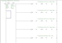
As an example (attached), what does TOP mean? I have other instances where they use TO before the constants. If it was T0, then I would take it as a timer command, but TO has me stumped.

I still don't really understand the entire row of K values either!

Going to be an uphill run this one

Code.jpg
 
As an example (attached), what does TOP mean? I have other instances where they use TO before the constants. If it was T0, then I would take it as a timer command, but TO has me stumped.

I still don't really understand the entire row of K values either!

Going to be an uphill run this one

TO/FROM instructions are used to communicate with intelligent modules for Mitsu, like your temperature control module, i.e. anything that is connected to either left or right side of base unit (like A/D modules, hi-speed counters, Profibus modules, temperature sensors etc., everything but I/O modules)
when you add -P to instruction that means it executes once, when X30 and M15 go from OFF to ON. It's common way to initialize some things.

K indicates integer constant (whole number, both negative or postive).
If you look help for TO instruction you see how it works.
Intelligent modules have internal buffer memory, and also their head adress, which indicates where are they located in PLC configuration (simplifiedly speaking, first on the right has head address 0, next one has 1, and so on).


This is indicated as U/G in Mitsu, where U is head, and G is buffer memory adress.
So in your first TOP instruction you're accessing U0/G208 (manual says it's input range for CH1), first module on the right and it's buffer memory register 208.


3rd value is value you're writing (can be a register or array of registers, but also a constant), in this case it's 2.
4th value says how many registers do you want to fill, in this case it's 1.
If, for example, 3rd value was D100 register, and 4th K3, then you'd fill internal buffer memory registers 208, 209 and 210, with values located in registers D100, D101 and D102.
You can also write one register multiple timaes (copy value of one register few times in neigbouring registers in buffer memory of module).

Same goes for rest of your code.


I suggest you download manuals you need here, by ticking appropriate boxes:
http://app.mitsubishielectric.com/app/fa/download/search.do?kisyu=/plcr&mode=manual
 
As an example (attached), what does TOP mean? I have other instances where they use TO before the constants. If it was T0, then I would take it as a timer command, but TO has me stumped.

I still don't really understand the entire row of K values either!

Going to be an uphill run this one

TOP is a pulsed TO command. The FX uses TO/FROM commands to configure and read out from the extension modules connected on the right side of the main unit. The P after the TO signifies the pulse form of the instruction meaning it will only happen once for each time the preceding rung conditions go from false to true.

T0 (zero) would be a timer.

The K values after the TOP command are basically this.....

The first K0 signifies the first extension module on the right of the main unit.
The second part, (K208) is the buffer memory location, the third, (K2) signifies the configuration desired, and the last part is usually the number of words to transfer.

I am pulling this from memory so forgive me if its not clear. You can get all the information you need by downloading the manual for the extension unit you are using. It will contain an explanation and programming examples for what you are asking and more.


Hope this helps.
Dave
 
Thank you guys. Very helpful.
I have kinda been dropped in a hole fixing these machines, but I am making far better progress than I thought I would.
I have asked for a professional to come in and do the programming.... but apparently that isn't going to happen.
So I will plod on.
Many thanks for the help
 
I am making good progress. Your explanation above has helped greatly.
One part of the code I cannot seem to work out (or find) is the retrieval of data from another module.

The setup is as follows (looking at the modules top to bottom on the vertical din rail)

FX3U-4LC Pid controller
FX3U-64M PLC
FX485ADP
FX3U 4AD-TC

The info you gave me has allowed me to find the command to communicate with the 4LC Pid controller.
I cannot see where the comms to the 4AD-TC module are? This has a further 4x temp sensors attached to it.

As you mentioned the first K0 variable was the module number for the Pid controller. I expected to see K1 somewhere for the other module, but there isn't one.

I would post all the code... but its huge!
 
Okay, vertical DIN rail, I think LC is connected to the right, others are then connected to the left side of main unit, should be like this.

Didn't want to complicate it yesterday, but modules on left side are addressed bit differently than those connected on right side. :D
There's no TO/FROM, rather they're assigned special addresses in CPU module.

Check out memory locations M8260 to M8299, and D8260 to D8299, you should be seeing those locations being used.

Check this manual:
http://dl.mitsubishielectric.com/dl/fa/document/manual/plc_fx/jy997d16701/jy997d16701p.pdf
 
Ah thanks Doomsword. That makes sense.
I should add that this PLC does not run anything critical or dangerous... if it did, then I would not touch it.
 
Found those commands... getting my head around it slowly.

In the GP Pro-EX software, a couple of the touchscreen buttons have a bit address:

[#INTERNAL]LS104100

Is this bit stored internally in the screen module?
If so, then how/what retrieves that data from the main FX3U-64M PLC?

In the PLC code, I assume [CMP is compare?

Update... OK. its an internally stored bit switch. So what command would read that state from the PLC?
 
Last edited:
Well I have just about sussed all the problems out with this system. Many thanks for everyone's assistance.

I have just a couple of items I cannot seem to work out... last questions I promise.

When you press a screen button, it sets a bit [#INTERNAL]LS104000. This 'latches' that bit on, and opens another pop-up window using the bit set command.

However, to exit that pop-up screen, it uses bit reset at address [PLC1]400051,00 ? Why is it not the same address as the bit set?

What are the extra two zeros after the comma? (400051,??)

On that pop-up screen, there is a value up/down button.
These buttons write a bit momentary to [#INTERNAL]LS102000 and [#INTERNAL]LS102100. I cannot see where the PLC is reading these values after you have left the screen.

Finally (promise).. Lag. Wow, the system is laggy.
The touchscreen controls 2x machines over Modbus. However, if one machine is not plugged in (which happens alot), then the console becomes madly slow to respond to touch commands.
I am guessing it is constantly looking for that missing machine and timing out? The timeputs I believe are already set as low as possible.

Is it possible to command the modbus to only start comms with a particular PLC, if a certain bit is set? (as in, the machine is on or off).

Thanks all
 

Similar Topics

The company I work for asked me to program a simple PLC (Apparently since I'm a computer programmer, it should be easy for me). Anyways, I...
Replies
28
Views
5,898
I just started using plcs and had a plc crash due to a surge. I need to download the program again but it wont let me connect to the plc. I have a...
Replies
18
Views
4,616
I'm being tasked with supporting / upgrading these panels but no software, cable, documentation. I have an old laptop running XP and would like...
Replies
4
Views
1,996
Hi everyone, I'm trying to perform a serial download with a Total Control Quickpanel jr (QPK-2xxxx) using an old computer running QuickDesigner...
Replies
3
Views
1,696
Does anyone know where I might get a copy of development software for a TCP HMI?
Replies
4
Views
2,286
Back
Top Bottom