Trying to learn something new

peoplehouse

Member
Join Date
Jan 2009
Location
California
Posts
117
Hello group, at work we predominately use PLC5's so the only software that I've worked with is logix5. We have a bunch of stand alone Automation Direct DL105's in our shipping fluid loaders. I discovered that we have the software! (Directsoft32)
I decided to create a project and learn a new language. I'm just a maint. dude but managed to figure that X and Y are discrete I/O and C = coil. (C being a bit of a word?) Here is where I get discouraged, V MEMORY LOCATION.
My problem is that I compare everything to Rockwell stuff. So is V memory kind of like an integer or binary word? AHHHH sorry folks, now I'm lost.
Anyways I've Googled, You tubed, searched archives here but the user manual doesn't quite explain what I need to know. I'm sorry that I am not more specific, just trying to understand something else than I:012/00 or N7:2/1
Thanks all
Jeff
 
I'm just a maint. dude

Same here. I'm a mechanical guy that is not tough enough for the service factor required.

but managed to figure that X and Y are discrete I/O and C = coil. (C being a bit of a word?)

Almost correct. "C"s are internal bits like Rockwell B3xxx bits. And yes there are some words (Vmem) that can be used to control / view / change the "C" bits. These Vmem can usually be accessed by their alias names. VC0 is the control word for the "C" bits C0 through C17. VC20 is the control word for the "C" bits C20 through C37. VC100 is the control word for the "C" bits C100 through C117. Ect. ect.

So is V memory kind of like an integer or binary word?

They can be. Numbers in Direct Logic can be confusing at first for somebody familiar with AB. Addresses are in octal (no problem for you there). The Data from timers and counters is in BCD (binary coded decimal). BCD limits the values in one Vmem to 9999. Some timers use a double Vmem for the accumulator (see my gotcha remark). Those timers (TMRA, TMRAF) can time to 99,999,999 in either tenths or hundredths of a second. You can change a number from binary to BCD or real it just requires you to use the right instruction. One down side is that it's up to you to keep it all straight (binary from BCD ect.).

Some of the other Vmem aliases are TA7 which is the alias for timer 7's accumulator (current time on timer 7). CTA22 is the Vmem alias for counter 22's accumulated counts. VX100 is the control word for inputs X100 through X117.

One common gotcha for a newbie Direct Soft programmer is the unintentional overlapping of addresses on accumulating timers and up-down counters. So if you use a accumulating timer like a TMRA or a TMRAF and assign it an address like T12 then you cannot use T13 as a usable address.
 
As suggested, the 'V' memory areay is undifferentiated as to number types. It is absolutely the responsibility of the programmer to keep track of how a given area is used (a BCD number, a 'binary' number (this is AD's nomenclature for the type of number you would see in an Allen Bradley 'N' register) or possibly a Real/Flaoting Point number. To further the complication some number types use one V register (16 bits long) or two contigous 'V' registers (double size BCD, 'binary' or a Real/Float). Again it is up to the programmer (I use detailed nicknames and descriptions to keep this staight) to not use the second word of a two word value for something else.

You will also note a variety of Add, Subtract and other operations. These are differentiated by the type of operand espected and result to be produced. In Allen Bradley a math operations could recognise the tyep of the operands and/or destination and take that into account. In the AD world it is totally the responsibility of the programmer. If improper operands are presented to an operation then garbage (GIGO) results.

Please persuse the information I provided at my site. Feel free to ask questions, preferably at this forum for the education of all.
 
First of all thank you for the replies and the links. This will take me a few days of reading and trying to understand. Today I downloaded my little 3 rung project into the DL105, wired 2 momentary P/B's to X0 and X1. I got it into run mode but for some reason the inputs did not change state. (It doesn't work) Almost like the processor wasn't scanning or something.
Tommorrow I will Post a screen shot, I must be missing something.
Thank you all again
Jeff
 
Just a couple of things to check,
Did you turn on show status? Is the PLC the plc is in run, Go to Debug then Data view and watch the value of your inputs.

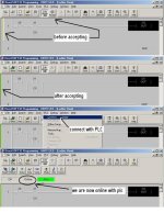
Looking at your srceen it looks like the yellow bar on the left is on meaning the program has not been accepted.

Hope this helps
 
Well, I had it in run and my indicator led's on X0 and X1 are good. When I turn on show status the only thing highlighted is..uh I think it was K5 on the timer. I didn't know about the data view, I will take a look.
Do I need to add power flow instructions? Something like this..

SP0
---| |---------|LD
|
|OUT

I downloaded the DL105 user manual today but I didn't see anything that says you need to start the ladder with a first pass instruction.
This is fustrating in a golf kind of way! Thank you
Jeff
 
The original post has a key statement (quoted below), at the end. The problem is that you've started with Rockwell, are firm in your Rockwell experience, and now, are trying to fit the 'rest of the world' into a Rockwell mold. Sorry, but it is not going to work out well. Actually, had you gone the other way (as many non-US guys do), you'd find out that 'the rest of the world' is pretty easy to move between platforms. Rockwell made (and it still making) the world their own oyster. NOT THAT THIS IS A BAD THING (as long as you never leave that world).

Good Luck.

Hello group,
.....
My problem is that I compare everything to Rockwell stuff. So is V memory kind of like an integer or binary word? AHHHH sorry folks, now I'm lost.
Anyways I've Googled, You tubed, searched archives here but the user manual doesn't quite explain what I need to know. I'm sorry that I am not more specific, just trying to understand something else than I:012/00 or N7:2/1
Thanks all
Jeff
 
Looking at your srceen it looks like the yellow bar on the left is on meaning the program has not been accepted.

As jseavers mentioned earlier here is a screenshot to show the difference.
online.jpg
This is fustrating in a golf kind of way! Thank you
Jeff

Perhaps these final screen shots will help
status.jpg

Edit: You can be online first before accepting either way you need to accept the edit and then load to the PLC before any powerflow will show up
 
Last edited:
Obviously I'm a bonehead.
Thank you all for your patience and I will post my results on Monday.

Vaughn, thank you for taking the time to create the step by step instructions.
Jeff
 
You guys are awesome!! Now my code is working. Thank you all very much. Now I can fianally move on. I will have more questions in the near future
Thank you all again,
Jeff
 

Similar Topics

Hi all, Got a new device I'm trying to work out how to communicate with. It came along on Monday morning after 9 months of development inside my...
Replies
19
Views
5,725
I am a water treatment plant operator tring to learn as much as I can about programming. We use TSX plcs (Quantum)and program ladder logic using...
Replies
1
Views
1,595
I am very familiar with AB PLC 5 and SLC500, however we have recently added a new system that has a contrologix 5000 in it. Is there any where...
Replies
4
Views
1,815
I have a S7 416 2DP and I am trying to get it to communicate to a 200. I guess anyone have any links so I can read the setup, I have my 5512...
Replies
10
Views
5,997
Hi everyone. I am trying to learn about PLC5/03's. I have set up an Inspiron 1100 laptop-->usb to serial port adaptor--> SLC 5/03 serial port. I...
Replies
1
Views
2,866
Back
Top Bottom