WAGO Controller and Maple Systems HMI Addressing

Eager Beaver

Member
Join Date
Aug 2021
Location
Sydney
Posts
10
Hello friends,

I’ve recently started learning about PLCs and HMIs after I acquired a Wago 750-871 with one digital input card and two digital output cards attached along with a Maple Systems HMI5080T.

I have also downloaded CoDeSys 2.3 with the relevant Target Support Package and am using EasyBuilder 5000 to program my Maple Systems/Weintek HMI.

Please forgive me if my questions are too simple but I have spent a week reading the Wago manual and have also been playing around with creating bit lamps but I just cannot seem to figure out what the correlation is between the two platforms’ addressing schemes.

I know that Wago uses the IEC 61131 format of %QX0.0 but everything in EasyBuilder refers to addresses such as 0x0000 or 3x0000 or 4x0000.

I have figured out that reading address 0x00001 will indicate the input status of port 1 on my 8-port digital input card and was successful in getting a lamp to “light” on the HMI when I applied 24V to it.

What I am not able to figure out is how to enable a digital output. I have two 8-port digital output cards which are just after the digital input card in the set. I have tried to setup buttons on the HMI which write to all kinds of addresses but nothing seems to work.

My background has been with microcontrollers such as Arduino and Teensy so I am still learning but would really appreciate any hints you can provide.

Thank you.
 
You need Modbus addressing.
Look for a manual that describes Modbus registers for the Wago controllers.
0-255 for Inputs etc.
Use Holding Registers if you can, both the controller and HMI can access those.
 
Sorry, I forgot to mention that but I’ve already had a look at the Modbus section in the Wago manual for the 750-871 here: https://www.wago.com/medias/m07500871-00000000-0en.pdf?context=bWFzdGVyfGRvd25sb2Fkc3w5MTMzMTU1fGFwcGxpY2F0aW9uL3BkZnxoOWEvaGI1LzEyMTk5OTI2MzY2MjM4L20wNzUwMDg3MV8wMDAwMDAwMF8wZW4ucGRmfDA5MDQwODMyNDJmMTY2M2IxNmY0NTU4Y2IwNTIyNDM5NTA1NjRkZjNlYjA1MTVkZTFhM2RhYjViYzEyYzFmYzk&attachment=true

According to the manual on page 235, it mentions that Holding Registers are for analog outputs only so I’m a bit confused. I believe I need to look at function code 5 or FC5 but am not sure how to convert the digital output address from the %QX0.1 to the 0x00000 format.

Cheers.
 
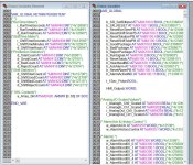
This was a PDF too large to attach on here, broken down to 2 JPGs.


Using the 4_xxxxxxx registers you should have access to pretty much everything on your Wago side.


Hope this helps.


Rock On!!

0_offset_Modbus_01.jpg 0_offset_Modbus_02.jpg
 
If you get a chance look up some PDF docs on their IPC's (Wago).
They have some good info on Modbus, Network Variables that can be shared across 2 or more of their controllers and addressing and such.
 
I mapped everything on the Wago controller to 4_xxxxx registers. No issue with the HMI reading writing.
Check out the Wago JPGs for the mapping.
By mapping via the controller I do not need to use the FCx Modbus codes for Read/Write and such.

It's sort of easy once you get it to work for 1 register.
Follow the mapping and watch out for 0 based or 1 based addressing.
Worse case scenario you'll be one register off, easy to fix.
 
Last edited:
I would set up as follows:
Set up some Markers as Push Buttons
%MW0 = 4_12288 (Modbus Register)

%MW0, (4_12288 Modbus Register as per PDF/JPG)


%MX0.0 = 4_1228800 (Register 4_12288, bit 00) Push Button #1

%MX0.1 = 4_1228801 (Register 4_12288, bit 01) Push Button #2

%MX0.2 = 4_1228802 (Register 4_12288, bit 02) Push Button #3

Use the mapped markers on the HMI (as addresses).


Then, on the Wago side set up something like:


IF %MX0.0 = TRUE
THEN
%QX0.0 = TRUE
ELSE
%QX0.0 = FALSE


%QX0.0 will only be true as long as %MX0.0 is true.
If you make the PB a Toggle , then you'll be able to toggle the output On/Off.
 
Last edited:
@bkottaras - thank you for posting all this information, I appreciate it.

I must admit, it is a steep learning curve for me but I'm doing my best to understand everything as I read more. 📚

If I understand correctly, are you suggesting that if I want to turn on a digital output, best practice is to enable a bit in the PLC's remnant memory area (described on page 87 of the manual as a "Flag" and I believe what you refer to as a "Marker") and then programmatically check that memory address and through the "IF" statement example above, control the output - instead of writing directly to the memory address which directly controls the digital output?

I would have thought it would be equally possible to enable an output directly because on page 87, it also states that there is read/write access for both the PLC and the Modbus with regards to physical outputs (for example, %QW0 to %QW255).

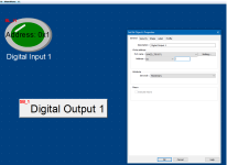
By the way, here are a couple of pics of my PLC configuration and a test screen that I've put together. The lamp works great, its address is 0x1 and when I apply 24V to port 1 on the digital input card, it lights up fine.

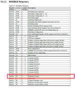
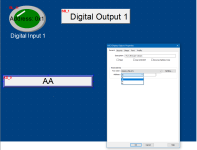
I also thought I would also start to learn how to read data from the PLC and that has also been difficult. For example, I wanted to display the PLC's firmware version on the screen and page 257 of the manual (screenshot 3) indicates that information is one word stored in address 0x2010. Of course, when I am in EasyBuilder, there is no 0x prefix, only 3x, 4x, 5x, 6x.

screenshot1.png screenshot2.png screenshot3.png screenshot4.png
 
Last edited:
0x prefix usually means hexadecimal radix, so 0x2010 is 8208 decimal (2*16**3 + 1*16**1, I am doing this in my head so an arithmetic error is likely).

3x, 4x, etc. is the MODBUS prefix that determines what type of data (discrete bits vs. analog 16-bit integers) and I/O direction (read vs. write)
 
Last edited:
I cut my PLC teeth on Modicon 984. Addressing was

0x for memory coils and discrete outputs
1x for discrete inputs (read only)
3x for analog inputs (read only)
4x for memory words and analog outputs
 
@drbitboy - that makes sense, thank you.

Does that mean if, for example, I wanted to read the firmware version in my example screenshot 4 above, I'd select 4x then 8208?
 
Are you using Ladder or text based editors ST for your programming?
If I get a chance I'll throw something very very basic together this weekend.
If you get the basics the rest will be a bit easier to understand as you move on.
 
@bkottaras - thanks mate! Coming from C I'm preferring ST for programming.

Hopefully I'll figure this out the more I experiment.

I've set 3 goals for myself as part of my initial self-training.

1. Create a lamp which lights upon digital input. done
2. Create a button which activates a digital output.
3. Read and display the PLC's firmware on the HMI.

1 was easy... 2 and 3 are looking more challenging.

PS: @drbitboy - I tried 3x8208 and 4x8208 with no success.

Thanks again guys for your help.
 

Similar Topics

I have been trying to setup a connection between a 1769-L33ER and a WAGO 750-881. The WAGO PLC is part of vendor equipment. I set up a Generic...
Replies
0
Views
1,162
Hi, I am thinking about to upgrade a wago plc-setup I use at home. I plan to switch my 750-880 (which only can be programmed with Wago I/O Pro...
Replies
11
Views
4,314
Hi all Have anyone used the J1939 or NMEA gateway mentioned in the following PDF from WAGO? www.wago.com/infomaterial/pdf/51188622.pdf On the...
Replies
0
Views
1,688
Hi. Just curiouos of the capabilities of the wago ethernet controller. Would it be possible to access/monitor it from a remote site using the...
Replies
5
Views
2,868
Hi all... I am currently working with WAGO Fieldbus Controller 750-841, it can be configured as a PLC. I have searched the manual and Wago's...
Replies
10
Views
7,177
Back
Top Bottom