Well, that's some thoroughly archaic stuff. You're putting a PanelView 1200 Classic back into service, on purpose ?
 I actually kind of like seeing old systems that have ran for 30 years and only need a swift kick to keep going. The company already purchased a replacement off ebay and had the unfortunate problem that the CRT died and took the program with it. I'm recreating the portions they used so they can get it running without purchasing even more expensive equipment or retrofitting and upgrading. the PV1200 apparently cost them barely anything.
Even though you aren't getting errors on the BTR/BTW instructions, check the block transfer control blocks for conflicts. When you use a chunk of an N-file instead of structured BT-file elements, the control block is 5 words long. So your BTW uses N130:15-19, and your BTR uses N130:40-44.
The program itself wasn't written by me, it was existing already. so that should be set and ready to go as is. and there are actually a bunch more BTR taking up the rest of the control blocks that are in order, by 5s. I believe they go from N135:0-N135:59 or somewhere around there (not sitting in front of the work laptop at the moment), but they were already in and working. with the previous PV
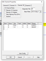
A PanelView can emulate multiple "racks" of RIO memory, in 1/4 Rack increments. But it's weird to start at Rack 6 in the last quarter.
that 1/4 in rack 6 is filled with extraneous Discrete Inputs, rack 7 group 0,1,2,3 are all Discrete IO coming in. and they used 4-7 for the Block transfers (Majory of block transfers were for Job recall, this isn't going to be used anymore, but the block transfers are still there, I'm just not adding them to the PV)
I suppose it's not impossible: the PLC-5 Scanlist appears to match match the configuration in the PanelView. I just don't see why you wouldn't use Rack 6 and Rack 7, both Full Racks for the discrete I/O, and then address your block transfers to use the higher group numbers.
The "Last Chassis" checkboxes are probably both OK. In my opinion it should be labeled "last Adapter", because it indicates that the PLC-5 Scanner channel doesn't need to scan the network for another physical adapter in that logical Rack. An example would be two 4-module 1794-ASB FLEX assemblies both set up as 1/2 Rack each... only the 2nd one would be designated as "Last [physical] Chassis [in this logical Rack]"
This is the only remote I/O in the system. although some things don't really match up for me visually, as they don't have any actual Input or output cards in the racks that I can see in the program, but this just feels like a lack of knowledge on my part as to how it can be configured. This was taken from a running system that only had the PV fail
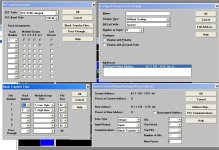
In the PanelView program, it doesn't care what R/G/S or what N-file the data came from or is going to in the PLC. To the PanelView, block transfer data is just an undifferentiated "File" of data tofu, numbered in your case File 1 and File 2.
PanelView RIO is an unusually low-level look at Universal RIO because you have to think about the parts of the discrete image that are used by the Block Transfers. Most ordinary block transfer devices like analog modules don't use the discrete I/O at all, so you just point your BT's at the actual Rack/Group/Slot location and they take over the bytes they need.
There are two analog input cards with block transfers further up
I think that you can actually send two Block Transfer Writes, and two Block Transfer Reads, to each "Group". They would be differentiated by the Slot number: low-byte is Slot 0, high-byte is Slot 1.
So you should have both Input and Output data in what the PanelView thinks of as "File 1", of 32 Words each.
That is what my assumption was based on the description left by the original programmer, and that the N file 135 is only 32 words long. so it had me wondering whether or not I needed to use Rack 7-Group 7- Low byte only, or needed both. Neither configuration gave me any block transfer info into the PV display (while the Discrete still worked fine)
If you want to use File 2, you will set up another pair of BTR and BTW instructions, addressed to Rack 7, Group 7, Slot 1.
Makes sense, so with the first BTR/BTW I would only need to use Low byte to get to slot 0 (or module 0 as its shown in the BTR/BTW)
I cannot remember for certain if the PanelView's terminology of "Input" and "Output" is from the perspective of the PLC or the perspective of the PanelView terminal.
Panelview Input addressing goes to the PLC Input addressing. Panelview Output addressing reads the output in the PLC of that RIO Bit. (I've got some Indicators that use the complimentary Output from the Input to show status)
I think that a Numeric Data Display would be "Output" data that is written to the PanelView with a Block Transfer Write.
This is actually a really good idea, I thought I had tried that but I may have been messing with multiple other parts of the configuration instead of following the "1 change at a time" rule... after all, if it wasn't yielding results then you'll end up changing other things as well right.
ANY OF THIS COULD BE WRONG: this was second-nature to me 15 years ago, but I simply haven't used a PanelView 1200 or 1400e since I closed the door on the demo closet at the RA office in the spring of 2011.


