Flying Shear Controller Cutting Acuuracy

rahni

Member
Join Date
Oct 2012
Location
tehran
Posts
10
Hi All, I Have a question, I am very thank full to you if help me,

I designed a flying shear controller based on fpga and microcontroller,

but the cutting error is more than 5 mm,

i want to reach cutting error to less than 1 mm,


{

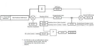
The attached control block diagram is as same as control techniques documents,

best possible sample time of main loop is 2 ms,

all calculations are floating point for ease of operation // it seams it is better to change to integer for higher man loop speed
}

The main question : the control loop is optimum or not?
Thanks again for your valuable time
loop.jpg
 
The block shown appears to assume this is done in a Control Techniques Unidrive, probably on the motion module. I can't tell if this is the actual platform or if this diagram is just a model for a controller implemented on a different platform. I'm pretty sure Control Techniques has a canned flying shear implementation that you can get from them. That might be the way to go.

Is your error always in one direction or is it bipolar? Where in the profile does the error occur and what is the shape of the error value relative to the move profile?

A couple things catch my eye:
1) Are you sure your Kvff value is set to the optimal value?
2) There is no acceleration feed forward torque term from what I can see. This would be a very good thing to have.

Keith
 
if done with microcontroller the scantime is way faster thus accuracy is far better.
get the speed from external encoder, make in your controller a array with speeds, and encoderdistances the shear needs to have to cut on correct position.
lets assume runningspeed is 1m/s
so the scantime of 2 ms will give you a max accuracy of 3 mm.
with a correct calibrated arduino you can get to the resolution of the encoder used.
The motor will need a certain time to speed up,
so the table has for 0.5 a value for example of 12 emcoder
for 1 m/s 18
for 2 m/s 32 steps etc.
 
The block shown appears to assume this is done in a Control Techniques Unidrive, probably on the motion module. I can't tell if this is the actual platform or if this diagram is just a model for a controller implemented on a different platform. I'm pretty sure Control Techniques has a canned flying shear implementation that you can get from them. That might be the way to go.

Is your error always in one direction or is it bipolar? Where in the profile does the error occur and what is the shape of the error value relative to the move profile?

A couple things catch my eye:
1) Are you sure your Kvff value is set to the optimal value?
2) There is no acceleration feed forward torque term from what I can see. This would be a very good thing to have.

Keith

Thank you Keith for your response

It seems the error always is in one direction, for your other questions, maybe my calculation is the source of error,

PP_Math=Proportional_Gain/100.0; //kp

Car_Vel_FF_Math=2048.0/(Max_Real_Carg_Velocity_float/(60.0)*Line_Pulse_m*Sample_Time_ms*Line_Average_Number/1000.0);//Kvff

for example if max carriage velocity is 110.9 meter/min
line-pulse-m is 72150 pulse/meter
sample_tmie = 2ms
Line_Average_Number = 10 that means line speed averaged at 20 ms then we have Car_Vel_FF_Math = 0.76786

Car_Vel_FF_Term =(int)(Filter_Line_Velocity * Car_Vel_FF_Math);
if(Car_Vel_FF_Term>=Max_Output)Car_Vel_FF_Term=Max_Output;
Pos_Error=Product_Length - Desired_Length; // in pulses
Proportional_Term = (int)(Pos_Error * PP_Math * 1.0);
if(Proportional_Limit==0)Proportional_Term=0;
else if((Proportional_Term>Proportional_Limit)&&(Proportional_Term>0))Proportional_Term=Proportional_Limit;
else if((Proportional_Term<-Proportional_Limit)&&(Proportional_Term<0))Proportional_Term=-Proportional_Limit;
float_Car_Cruise_Output =(int)(Proportional_Term+Car_Vel_FF_Term);
if(float_Car_Cruise_Output >= Max_Output) float_Car_Cruise_Output = Max_Output;
 
if done with microcontroller the scantime is way faster thus accuracy is far better.
get the speed from external encoder, make in your controller a array with speeds, and encoderdistances the shear needs to have to cut on correct position.
lets assume runningspeed is 1m/s
so the scantime of 2 ms will give you a max accuracy of 3 mm.
with a correct calibrated arduino you can get to the resolution of the encoder used.
The motor will need a certain time to speed up,
so the table has for 0.5 a value for example of 12 emcoder
for 1 m/s 18
for 2 m/s 32 steps etc.

Thank you shooter,
data acquisition from encoders is done by fpga, and control loop is run in micro, because of my floating point calculation total control loop run time is 1.2 msec and I closed the loop at every 2 msec, do you say if the control loop scan time be less than 0.5 ms the drive and motor can respond?
 
I don't have enough information about your system to know if your velocity feed forward multiplier is correct or not. However, assuming that the Filter_Line_Velocity is truly a velocity (units/sec or units/min) there seem to be some numbers in your calculation I don't quite understand.

You indicate that the error is always one direction. Which direction?

What is developing your position command value? Are you confident that is correct?

Keith

Always the error is more than which is preset, for example the desired length is 6000 mm but actual is 6005 or 6006.
My main question is if Kff * Vline + kp * error that error is difference in actual and desired length is adequate for position loop or not? integral term is needed or not? what is the best algorithm to have same velocity at desired length,
is 2 msec cycle time adequate for position loop or not?
 
My main question is if Kff * Vline + kp * error is adequate for position loop or not? [error is difference in actual length and desired length]. integral term is needed or not? what is the best algorithm to have same velocity at desired length,
is 2 msec cycle time adequate for position loop or not?
 
Last edited:

Similar Topics

I'm working on a flying shear application consisting of two kinetix 350 drives. I need to find a way to connect the encoder connected to the...
Replies
6
Views
2,800
Hi All, I have been asked to look at a flying shear tube mill and improve on its accuracy currently running at up to +/- 3mm and needs to get down...
Replies
50
Views
19,674
Here is a nice flying shear application. This type of project is often asked about here...
Replies
2
Views
3,440
Hi, I'm new to PLC's...more of a PC and Labview person for 20 years...Question to you pros out there...We're building a flying shear machine (I...
Replies
2
Views
3,592
Hi.. I have flying shear application using rotary knife. The line speed is 100 FPM and rotary knife using Vector motor with Inverter for speed...
Replies
5
Views
6,461
Back
Top Bottom