Piggybacking 4-20mA Signals

ControlLogix

Member
Join Date
Feb 2003
Location
Southern Ireland
Posts
62
Hi guys,

I have a feeling I know the answer to this one already and while you guys will probably confirm this, I need a workaround!

I have pressure probes (20 in total, 1 per injection moulding machine) that are wired up to there respective Injection moulding controllers (industrial PCs). The signals going into the IPCs are 4-20mA signals. I want to "take a copy" of this signals to a new PLC which is being built for information gathering.

Now, somewhere in the back of my head, something tells me that I can't do this. I know I can do it with my digital I/O (it works well) but can somebody out there explain to me why not and what I can do about it.

Is it that I am not splitting the analog signal (i.e. going to two different sources) and thus reducing the current and sending spurious data to both the IPC and PLC?

Any help would, yet again, be very much appreciated,

Best Regards,

Colm
 
you can do it if you run them in a series loop AND the total loop resistance (wire + input cards) is not greater than that specified by the signal generating device (pressure probes in your case).
 
By the way, are you using an Analoge input DAQ card plugged in your industrial PC?
just want to know if ant body use this solution to operate machines.

Thanks
 
You can use a single 4-20 mA transmitter for multiple devices wired in series, subject to two conditions.

First, as shown above, you have to keep the maximum load within the limits of the transmitter allowable load. This is not usually a problem.

The second potential problem is that both devices may have the "-" side of the input tied to power supply "-". If that is the case the current will follow the path of least resistance back to the power supply and the second device in the circuit won't get the signal.

If either is a problem, you can still feed the current signal to two devices by using a signal isolator. M-Systems, Red Lion, Action Instruments, and many others manufacture these. You wire the transmitter to the isolator, then to one PLC in series, and then back to the power supply as shown above. The output of the isolator should then be wired to the other PLC.
 
NOTE: I deleted my last post as there were a mistake in the drawing (opposite polaity) and here is the correct one:

Greetings ControlLogix,

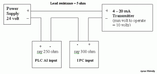
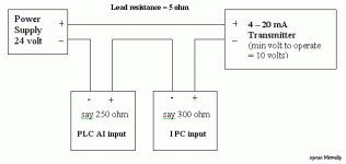
Sure you can connect multiple loads in series in a 4–20 mA tranmitter loop, It's OHM law. (See the figure below)
But you must take care of this formula:

Voltage drop on load(s) + min voltage to operate the transmitter < 24 volt (power supply)

Where, Load(s) are the sum of thr input impedance of inputs of your devices plus lead resistance.

Applying this to the example below: ( calculate for 20 mA which is 0.020 A)

0.020 ( 250 + 300 + 5 ) + 10 = 12.1 volts, which is < 24 volts then it is OK.

Remeber: Lead resistance must be taken into consedration and do not forget to multiply by two.

ohm law.gif
 
Tom Jenkins said:
The second potential problem is that both devices may have the "-" side of the input tied to power supply "-". If that is the case the current will follow the path of least resistance back to the power supply and the second device in the circuit won't get the signal.

Tom, I realized my mistake in the drawing so I reposted it again and then I read your post.

Now, Don't you think that the current configuration (the correct drawing) will overcome the potential problem?
 
ayman metwally said:
Now, Don't you think that the current configuration (the correct drawing) will overcome the potential problem?

No - the problem I was taliking about in the second item has nothing to do with polarity. Many PLCs (and some indicators and recorders) have the "-" side of all input channels tied to a common point on the input card. These are often referred to as "single ended" inputs. In most of these cases the "-" is also tied to the "-" power supply input on the input card. If either of these situations exist on the input card then the signal cannot be run in series to both input cards.
 
Tom's last comments are the reason why many PLC manufacturers tell you in their product literature that if you are going to connect multiple load devices on the same current loop, the PLC must be connected as the last load before the current returns to the common of the power supply. They usually don't explain why, however. Thanks for the explanation, Tom.
 
The polarity of the two 'PLC AI inputs' in Mr. Metwally's diagram (above) is reversed. The terminal going to the power supply negative should be negative; the terminal going to the (-) '1 PC input' should be positive.

Dan
 
I am thinking along the same lines as rytko.
How does current flow in the circuit shown?
Shouldn't it be connected +/-.....+/-.....+/-.... in series?
 
azecraze said:
I am thinking along the same lines as rytko.
How does current flow in the circuit shown?
Shouldn't it be connected +/-.....+/-.....+/-.... in series?

Answer:
Essentially, the concept is correct, the AIs are wired + - + -, but one typically 'starts' at the power supply +.

The transmitter gets the full voltage from the power supply: P/S + to transmitter +.

The transmitter (-) goes to the most positive terminal of one of AIs. That AI's (-) goes to the positive terminal of the next AI. +/-.....+/-..... as you put it.

That leaves the 2nd AI (-) terminal to be connected to the power supply (-) negative, which completes the loop.

Dan
 
OK guys, It was my mistake ..
I am reversing the polarties, Here is the correct one: (I hope)

Note: I meant by "IPC" : Industrial PC

ohm law.gif
 

Similar Topics

Hi all, I'm connecting several 4-20mA sensors together in parallel (only one shown below) The enclosure is ABS plastic with metal backplate DAQ...
Replies
5
Views
273
Problem: Our PLC can only output 4-20mA, but the actuators it needs to control, modulate based on a 0-135Ohm signal. Buying 4 or 8 individual...
Replies
7
Views
275
What's your go to 4-20ma isolator. I've got some 4 wire 4-20ma from several flow meters and scales that I would like to isolate before it gets to...
Replies
10
Views
1,692
Hi, I need to read three 4-20mA signals from a DCS(ABB) in a remote 6 channel analog input module with RS485 modbus port. When I connected...
Replies
2
Views
486
Hello this is my first post. Looking forward to being more involved in this community to learn and hopefully help others. Any help or guidance...
Replies
7
Views
790
Back
Top Bottom