c_gunner
Member
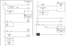
I have an application where I need to push a (car) shifter button to 2 different forces. I have taken a 5 position, 2 way center port blocked valve and piped it to my cylinder. The input air supplies are piped to a spring return valve. This valve is piped so that if I turn on the other valve, I apply low pressure. If I turn on the spring return valve and the center blocked valve, I apply high pressure. This part is working as I intended, albeit mechanically. The trouble I am having is programming related. No matter what I do, I can not make it alternate every other cycle with high then low (then high, then low) pressure (for 50,000 cycles). I use a load monitoring device to determine the load was met on the button. First pass I want 40 Newtons on the button. I turn on the first valve and I apply the load to the button (the spring valve is not ON at this point). Once 40 Newtons is met, I retract the cylinder. Next I want to apply the high load so I turn on both valves; the spring return switches over to 89N and the center blocked valve applies 89Newtons. then I retract the cylinder. then repeat 40 Newtons / 89 Newtons until the cows come home. I am using an OMRON CPM10 PLC and Syswin 3.4 software. My cylinder has a stroke of about 2" and I am utilizing switches to indicate position (advanced or returned) of the cylinder.
I am looking for a way for the PLC to recoginize 40N met, run 89N. 89N completed, Both 40 and 89 done, repeat. I can't figure out the cycle complete and what to use to repeat the test. I was using Keep/Latch statements to differentiate them, but my unlatch points are causing me problems. Bear in mind that the load monitoring device has two alarms. If I apply 40N, alarm one is on and sends a signal to my PLC. Same thing for 89N but alarm 2 is on, BUT 40N is also on. I think that is why I can't determine how to program the PLC to know the difference.
I am looking for a way for the PLC to recoginize 40N met, run 89N. 89N completed, Both 40 and 89 done, repeat. I can't figure out the cycle complete and what to use to repeat the test. I was using Keep/Latch statements to differentiate them, but my unlatch points are causing me problems. Bear in mind that the load monitoring device has two alarms. If I apply 40N, alarm one is on and sends a signal to my PLC. Same thing for 89N but alarm 2 is on, BUT 40N is also on. I think that is why I can't determine how to program the PLC to know the difference.


