Control Valve won't move

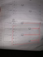
RTFM. Compare the manual instruction to your sketch. It is my opinion that the loop will never work until you make proper connection to the 0V terminal on the I/O card.
the 0v are all common and tied to each other internally. and his sketch shows the bottom terminal is making a connection to the 0v rail to the card 0v.
 
The worst ally to find a problem is to mistakenly believe you know where it is.

There are many other factors that can make a valve not move, not just the 4-20mA loop
 
Hi
RTFM. Compare the manual instruction to your sketch. It is my opinion that the loop will never work until you make proper connection to the 0V terminal on the I/O card.
His drawing is fine. The 0V are internally jumpered on that module. It's not isolated loops.
 
The drawing is fine....the 0V are internally connected.
 

Attachments

  • 20240221_095437.jpg
    20240221_095437.jpg
    148.1 KB · Views: 11
So here's the update. I checked amps from the card in series with the source wire while having the PLC attempt to send 100% open (20mA). I only got 4mA to read on the meter. This is strange to me because if the channel on the card was bad I wouldn't expect to see any current at all let alone a good value for the minimum position for the valve. Would this indicate a faulty channel or something I'm missing?
So, to get back to it.... do these things..

1) Set your output to 50%, you'll see 12mA regardless if it's a 4-20 loop. if you're seeing 4mA and its at 100%, that could just be scaled opposite in the program, i've done it before, not sure how yours is set up obviously.

2) check the output at the card (in series with your meter) and then at the valve (in series at the signal wire going to it). make sure they match once you can see your output correctly.

3) if you see no variance with 50% setting and still see 4mA. get a 250 ohm or 500 ohm resistor and unwire the valve at the card. install the resistor between the 0v and signal and check that you can see variable voltage when you change the output. you could even just put the resistor on one terminal and then hook up your meter in series to check amperage touching the open side of the resistor and the other side to the other open terminal (either 0v or signal depending on what you chose to put the resistor on).

4) if you see variance of voltage and/or mA but the valve doesn't move,. you can either decide the valve input is bad or you can get a sourcing meter/tester like the loop simulator i posted or you can get a fluke process meter that can source. then hook it up to your valve inputs and give it a direct known good output and see if it responds.


this is basically all you need to do to find where the problem is...

output at the card but not at the valve - bad wire
output at the card and at the valve both good - bad valve input or stuck
no output at the card - bad setting/program/card
direct source to the valve and no response - bad valve or stuck.
 
Thanks for all the feedback fellas. It turns out the wires were mislabeled in the panel which led me to believe the plc card was sending the correct amperage. However, I was looking at the wrong channel and have since found that the correct channel is not sending any amps. I am about to change out the card and see if that works.
 
Thanks for all the feedback fellas. It turns out the wires were mislabeled in the panel which led me to believe the plc card was sending the correct amperage. However, I was looking at the wrong channel and have since found that the correct channel is not sending any amps. I am about to change out the card and see if that works.
all the testing information still applies to see if it was a card issue or not. Installing the load directly at the card would allow you to test it without swapping. it's a good practice to do this to ensure there is no short in the loop causing problems, or voltage where it shouldn't be frying a card point.
 

Similar Topics

I have been requested to test this proportioning valve for PLC control of flow/pressure. Dwyer Series SVP Proportioning Solenoid Valve The flow...
Replies
10
Views
421
Hi there, We have a system at a water treatment plant where large raw water tanks feed into the plant that's all on the same level. At high tank...
Replies
18
Views
3,770
Working on a site where they are using a DeltaV DCS system. They are using Topworx DVC6200 controllers on their modulating valves. These control...
Replies
1
Views
1,067
Does anyone have any experience in this? I have a lead lag pump setup for water that is maintained by pressure using VFDS, the idea is to have...
Replies
6
Views
1,837
We have a project that has existing proportional valves and joysticks that they're using. The customer wants to eliminate the controller/driver...
Replies
6
Views
1,745
Back
Top Bottom