

So I'm pretty green when it comes to troubleshooting in the field so bear with me. We have a Danfoss valve that opens/closes from an analog output card in a remote PLC rack. I can see that we are trying to send full open (20mA) from the program but the valve will not move. Could someone explain step-by-step the process to check amperage from the card to see if it is actually sending 20mA? I'm trying to not blow anything up if I can help it. And yes, I have a process meter that can simulate amps. Also, I know it's not a bad Danfoss valve because it is only showing 1.845 mA via interface of the valve.
You are using an out of date browser. It may not display this or other websites correctly.
You should upgrade or use an alternative browser.
You should upgrade or use an alternative browser.
Control Valve won't move
- Thread starter TheColt46
- Start date
Mas01
Member

You don't say which PLC you've got, but in any case, you could try this...
1. You need to identify the (usually) 2 wires in the terminal block which sends the 20mA to the valve (maybe you've got an "I/O Spreadsheet" showing which terminals/wires are connected to each field device).
2. Disconnect the wires that go out from the PLC terminal block to the valve.
3. Set the Fluke/multimeter to read mA.
4. Connect probes of Fluke to the terminal block.
5. On your HMI (or however you adjust the valve position) move the valve over its full range (this will be either 0-20mA or 4-20mA, depending on how you've got it configured).
If the AO is correct, you should see the correct reading on the Fluke.
If the AO is correct, you will need to trace the wire routing to the valve. Is it routed via an intermediate junction box? Could that be the problem (loose wire, water ingress, etc)? etc.
Last edited:
So I'm pretty green when it comes to troubleshooting in the field so bear with me. We have a Danfoss valve that opens/closes from an analog output card in a remote PLC rack. I can see that we are trying to send full open (20mA) from the program but the valve will not move. Could someone explain step-by-step the process to check amperage from the card to see if it is actually sending 20mA? I'm trying to not blow anything up if I can help it. And yes, I have a process meter that can simulate amps. Also, I know it's not a bad Danfoss valve because it is only showing 1.845 mA via interface of the valve.
I'll try to elaborate a bit more on what Mas01 tried to say, as it wasn't very clear for someone who may not have ever done any testing.
There are multiple ways you can check a 4-20 signal output and verify it's at least coming out and/or scaling right for the called output.
If you don't know exactly what % output it's supposed to be, you'll be in trouble. but otherwise you can still do these and see changes and verify you have output.
There will be a couple of wires for your analog output. you only need to deal with the 1 signal wire if you are using a meter in series to check.
1) disconnect the signal wire from the Analog out. usually the return line is labeled 'Ret' or 'Return', you can leave it on.
2) take the leads of your meter and put them in the mA and Com positions. then set the meter to mA reading.
3) connect 1 lead to the wire you disconnected, and the other wire to the terminal you took the wire off of. the meter should be in series with the connection that was there before. if you connect in parallel you'll just blow your meter fuse.
The second way to test an output is to take the signal and return wires off. and install a 500 ohm resistor on the signal and return lines.
now use a meter and test DC Volts. this converts the signal from 4-20mA to 0-10 Vdc. so 4mA = 0v, 8 mA = 2.5v, 12mA = 5v, etc etc.

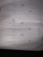
Thank you both for your help. It appears my source wire goes directly to the field from the output card so I'm going to check current from the terminal down there. One other question, I've attached the schematics for the valve because I'm curious if the DV-402.28 is a loop module that could also be the issue.
Attachments
I find that a "Loop Cal" was the tool to have to check things like valve, Make sure you get on that "Sources" & "Sinks"
Random Exzmple
Random Exzmple
I think you may mean Source and Simulate. Sink and source are terms for determining + or - common for a digital input. or in other words how an input card in wired. Source inputs require a - signal return and the card has a common +. and Sinking inputs require a + return and are - common.I find that a "Loop Cal" was the tool to have to check things like valve, Make sure you get on that "Sources" & "Sinks"
Random Exzmple
When you look at an analog signal, you can source the loop, which provides power and can be wire directly to an analog input. or you can simulate a device which goes in line with a loop power source that acts like a device in a chain of the loop, which goes back to an input.
In this case he could test the valve itself with a loop testing device like this one.
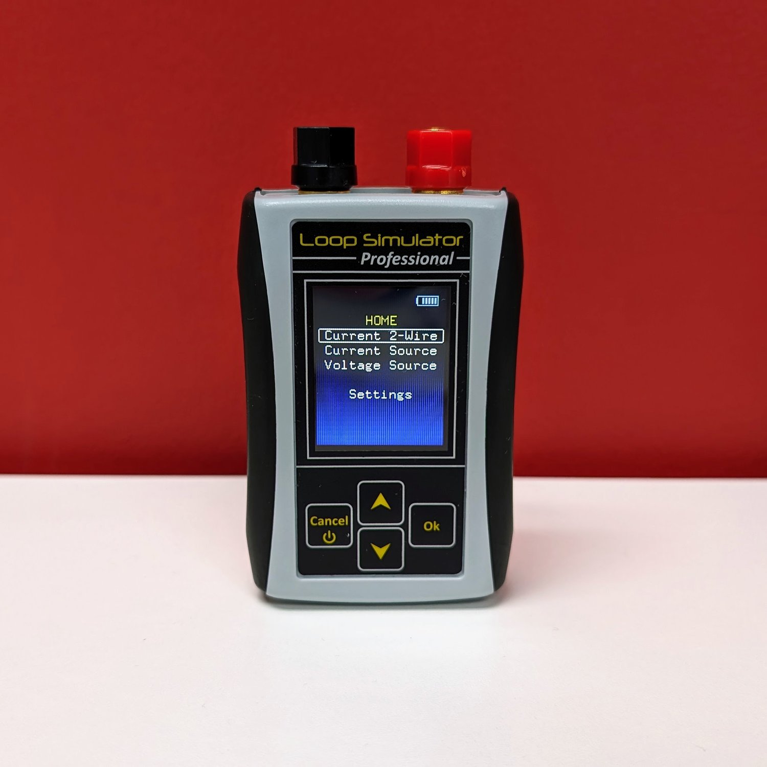
PLC Tools SIM-ALP2 4 To 20mA Analog Simulator And 0-10VDC Generator — PLC Tools - Simulators and Testers
SKU: SIM-ALP2 UPC: 695937858222
 plctools.com

But a quick test of in series current and/or using a resistor to convert to voltage will work quickly before getting to the point of wondering if the valve analog input is bad.
This schema does not answer the question of whether the valve has the correct electrical supply.Thank you both for your help. It appears my source wire goes directly to the field from the output card so I'm going to check current from the terminal down there. One other question, I've attached the schematics for the valve because I'm curious if the DV-402.28 is a loop module that could also be the issue.
Mas01
Member
I would first try to confirm that the PLC's AO is as expected.Thank you both for your help. It appears my source wire goes directly to the field from the output card so I'm going to check current from the terminal down there. One other question, I've attached the schematics for the valve because I'm curious if the DV-402.28 is a loop module that could also be the issue.
Eliminate that, then move on to other possible causes of the problem.
Tom Jenkins
Lifetime Supporting Member
4-20 mA is a loop. Your diagram doesn't show the connection from the - terminal of the valve to the 0V terminal on the output card. You have it wired as if it were a discrete command with a shared neutral. Check the PLC manual for the proper wiring configuration for an analog output.
So here's the update. I checked amps from the card in series with the source wire while having the PLC attempt to send 100% open (20mA). I only got 4mA to read on the meter. This is strange to me because if the channel on the card was bad I wouldn't expect to see any current at all let alone a good value for the minimum position for the valve. Would this indicate a faulty channel or something I'm missing?
+14-20 mA is a loop. Your diagram doesn't show the connection from the - terminal of the valve to the 0V terminal on the output card. You have it wired as if it were a discrete command with a shared neutral. Check the PLC manual for the proper wiring configuration for an analog output.
A current source can try it's best to generate a particular current. Most 4-20mA output cards are designed for a SINGLE 4-20mA receiver, and has the necessary impedance(Usually 250Ohms) to support 4-20mA current flow. If you try to put the 4-20mA current source on a much larger resistance than the nominal, you will risk a fall in current output which seems like your symptom.Would this indicate a faulty channel or something I'm missing?
Which analog output card are you using? Which analog valve are you using?
I would recommend reading up the wiring manual for your 4-20mA output card, and the wiring manual of the danfoss valve to check how to make a segmented loop for this actuation.
Essentially: DV-402.28 (2) needs to be connected to Wago Rack 5 Slot 6 Port 4 rather than the 24V Common. Same for all other devices if you want to get correct control.
Last edited:

So here's the update. I checked amps from the card in series with the source wire while having the PLC attempt to send 100% open (20mA). I only got 4mA to read on the meter. This is strange to me because if the channel on the card was bad I wouldn't expect to see any current at all let alone a good value for the minimum position for the valve. Would this indicate a faulty channel or something I'm missing?
If it's a reverse acting valve (signsl to close), then 100% could be 4ma. Send it 50%. You should get 12ma no matter which way its scaled.
Tom Jenkins
Lifetime Supporting Member
RTFM. Compare the manual instruction to your sketch. It is my opinion that the loop will never work until you make proper connection to the 0V terminal on the I/O card.
Similar Topics
I have been requested to test this proportioning valve for PLC control of flow/pressure.
Dwyer Series SVP Proportioning Solenoid Valve
The flow...
- Replies
- 10
- Views
- 422
Hi there,
We have a system at a water treatment plant where large raw water tanks feed into the plant that's all on the same level. At high tank...
- Replies
- 18
- Views
- 3,773
Working on a site where they are using a DeltaV DCS system. They are using Topworx DVC6200 controllers on their modulating valves. These control...
- Replies
- 1
- Views
- 1,072
Does anyone have any experience in this?
I have a lead lag pump setup for water that is maintained by pressure using VFDS, the idea is to have...
- Replies
- 6
- Views
- 1,839
We have a project that has existing proportional valves and joysticks that they're using. The customer wants to eliminate the controller/driver...
- Replies
- 6
- Views
- 1,748