another clock lab question

zofofg

Member
Join Date
Sep 2013
Location
joliet
Posts
1
Hi, obviously new here and I hope I pose this question correctly. Ive been reading thru and trying to make sure this comes out right. Our lab in class is as follows

1. Use a 24-hour presentation
2. Time will be presented in an Hour-Minute format (HH:MM) – no seconds.
3. Use the thumb-wheel switches and a PB to enter a time HH:MM format.
4. Have clock start at 12:00 when first set to program mode.

Ive figured most of this out but am stuck and was hoping you guys could give me a nudge in the right direction. Ive figured out how to move the thumb-wheel numbers over to the clock and i think I know how to have the clock start at 12:00. the problem I am having is I get the thumb-wheel to move with the PB but it doesnt stay over in O:6 it just flashes and program goes back to timing. I need that thumb-wheel number to stay and integrate into the timing. I am just looking for a nudge in the right direction at what i might need to be trying. Not looking for answers yet LOL Anyway I am using the TLP LogixPro Simulator and here is a copy of what I have programmed so far
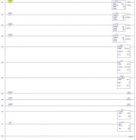
LadderRungs.jpg
 
I am just looking for a nudge in the right direction at what I might need to be trying. [I am] Not looking for answers yet LOL Anyway I am using the TLP LogixPro Simulator and here is a copy of what I have programmed so far.
Zofofg,

You need to add two functions to your program.

1. Add one rung that uses the First-Scan bit S:1/15 to set your "clock" (BCD Output Word O:6) to be equal to "1200" as instructed by Instruction Number 4. Instead of setting O:6 directly, set the HOUR Counter C5:2 Accumulator to "12" and the MINUTE Counter C5:1 Accumulator to "0".

2. Add two rungs that use Pushbutton I:1/0 to reset the Clock (Output Display O:6 in the BCD format). Instead of setting O:6 directly, set the HOUR Counter C5:2 Accumulator to (whatever you enter in the left 2 digits of the I:5 BCD Input Word) and the MINUTE Counter C5:1 Accumulator to (whatever you enter in the right 2 digits of the I:5 BCD Input Word). You will have to use the FRD instruction to convert the BCD value in I:5 to a binary number.

3. The last section of your program should be the rungs you have now that are supposed to create a 24-hour Clock using the LogixPro built-in Binary-Coded Decimal Display for Output word O:6. To do that you need to first get your counters set up properly. Your Counter Reset rungs are all wrong. For each counter, you are resetting it on EVERY PLC scan! That will prevent the counters from ever counting up past 1. Use a conditional instruction in front of each RESet instruction to ONLY reset that counter when you are finished using its Accumulated value. For example, the SECONDS counter C5:0 should only be reset AFTER the MINUTES Counter C5:1 has been triggered by C5:0/DN. In other words, move (drag) your rung 0007 up and drop it on rung 003, so that it is inserted between RUng 002 and 003. Then add the C5:0/DN in front of the old Rung 007 (new Rung 003). Do the Counter C5:1 the same way. C5:2 should be reset AFTER the Multiply, and by using the C5:2/DN bit.

Your new next-to-last rung in your program (replacing old Rung 011) should be a TOD. The TOD instruction converts the binary number in N7:1 to a Binary-Coded-Decimal number, so that it can be displayed correctly in BCD Output word O:6.

Let me know if you need more help. I have the program working now.

TIP: While you are testing and de-bugging, set Timer T4:0.PRE to "1" to speed up your clock, so you will not have to wait forever to see how the clock is running.
 
Last edited:

Similar Topics

i have tried to program my S7-300 PLC for the clock function but i cant get it to work can someone give me an easy example of one (i prefer with...
Replies
6
Views
3,969
Hi, The hardware is: Click Plc model # CO-O1DD1-O HMI model # S3ML-R magnetic-inductive flow meter model # FMM100-1001. I will set the flow meter...
Replies
4
Views
135
So I had an odd request from a customer for the above. I have written the logic and tested it all in one PLC with only using 7 outputs and 7...
Replies
15
Views
427
Hello I need to message read the entire 16 channel raw analog inputs from a 1769-L33ER Compact Logic controller to another 1769-L33ER Compact...
Replies
8
Views
244
I am noticing a problem where i am using MOV instruction and writing literal text into source and String datatype in destination. It works fines...
Replies
6
Views
486
Back
Top Bottom