How do you create a ladder diagram from concept

For any programming task I always start with an I/O point list. Then I create a list of alarms, and then a list of adjustments accessible to the operator. Finally I create a functional description that describes in text the sequence of operations and control functions for the system. This will be based on the loop descriptions in your spec, in your case.

Then start writing the program. Use descriptive names for each coil, contact, etc. and lots of comments on each rung. The comments should relate back to the function description.

Group program functions. Put alarms in one section, and control in one section, etc. Keep logically related steps together. I avoid one shots and set/reset as much as possible because they can be hard to debug.
 
Shosh,

this is what i do. but everyone will have their own style of doing things. it may be a little repetative, but in the automotive industry, you have to read between the lines sometimes.

1. make a copy of the specs.
2. read the specs
3. re-read the specs and look for key words MUST, SHOULD.
must means you have to, should means a recommendation.
these will bite you if you are not careful.
4. read the specs again and write down on paper the machine sequence. noting sensors, cylinders, analog signals, lights.
highlight the specs in green - yes this is ok. Pink for we need clarification, Orange for caution, Red underline for cannot do or did not quote. Pink, Orange and red must be discussed with the boss. he will then call the customer.
5. IMPORTANT ! get with the mechanical designer to see what his plans were for the system. many a time i have seen a mess because this step was left out.
6. take your notes and develop your i/o.
7. write your code (automatic cycle) and ask how the plc will know when things happen. when to start, when to stop.
8. ask what if questions, what if you do this instead of that.
you need an answer. you can never say the operator will never do that. if you think of it, it will happen.
9. write your manual code.

ALWAYS REMEMBER !
management don't care about how the machine is programmed, it has to work.

BUT !!
maintenance has to live with your code. make it as user friendly as possible and document it well. find out what maintenance is use to. what plcs do they have now.

IF you write the code that only you can understand, the machine will never run production, management finds out, they call your company and yell at your boss, and guess who has to rewrite the code and baby sit the machine 24 hours a day.


regards,
james
 
Thanks for the help.

Do any of you by chance have any examples or materials (links, books) that would go over this? I've gone over a bit of material on PLCs, but none of them really go over any methodology on how to design LD from specs. I've always had to wing it with trail and error without any organization.
 
i doubt anyone will send / publish any specific information.
for my part, ALL of my project specifications is considered company confidential. i can post here and discuss problems in general terms, but no specifics.
search my posts for example of fifo load / unload.

at the top of the page you will see online tutorial click here to enter.
go there for examples and tutorials.

regards,
james
 
I like to break all the bits of the process down to component level. A motor for instance has its own logic for handling the io, alarm conditions, manual control, auto sequence control & plant interlocks. That block once written can be repeated for like plant... Repeat for instruments, valves etc...

Once all your small bits are there, join them together with the primary seq / process...

If you gave a spec to a 100 different software guys, you would end up with 100 variation.. Thou all providing the requirements
 
Last edited:
Program structure:
Try to divide it in sections:
-initialisation block (executed if firs task)
-common tasks (processing analog, processing forbbiden states (MIN and MAX at the same time, setting validation..)
-communication with partners if networked
-automatic TASK
-manual mode
-test mode
-transfering output tags to real OUTPUTS regarding mode chosen
-alarms (list, ptiority, autoreset, manual reset)
-reset block (to put process in "home" position after error or alarm)
-animations in HMI screens


Then try to separate automatic task into few small "areas".
Each area has for inputs: "own" Inputs, own settings, inpusts from other areas that affects this particular area..
Each area has for outputs: "own" outputs, own states, own alarms.

Example: there are two cylinders, second one is activated after first one reaches end position.
Outputs of this area 1 (Cyl1) are "position reached", "out_cyl"...
Inputs of area 2 (Cyl2) are Cyl1.end_postion, Cyl2_home_position,...

So Cyl2 starts forward if:
Machine.Auto AND Emmergency.OK AND Cyl1.end_position AND Cyl2.home_position.
Cyl2 stops if notEmmergency.OK OR Cyl2.end_postion (it does not stop if notMachine.Auto because it must finish cycle first ..)
 
Last edited:
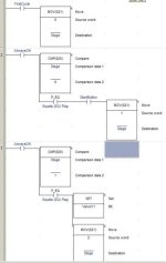
Thanks for all your answers. But lets do a simple setup. I got this from a book. This would be a description for a batch process. first what I usually do is write a description.

1. Push start PB
2. Open Valve V1 until 250kg of product A have been added
3. Start Mixer blade
4. Open Valve V2 until 310kg of product B have been added.
5. Wait 120s
6. Heat to 80C and maintain at 80C for 10mins.
7. Heater off. Allow to cool to 30C
8. Stop Mixer blade
9. Open drain valve V3 untile weight less than 50kg

What I usually do is go through the description one by one, and create a corresponding rung with each item. Now this would be schoolwork, and I know that you'd have a completely different process in industry, since you're doing hundreds of I/O's for each workcell.
 
If Stage=0 and Start.pressed -> Stage=1
If stage=1 -> set V1.Open -> Stage=2
If stage=2 and V1.Opened -> Stage=3
(option: Is Stage=2 and timer.max elapsed -> Alarm "V1 blocked" and stage=0)
If stage=3 and Weight=250kg -> set V1.close -> Stage=4
Is stage=4 and V1.Closed -> set MixerBlade -> Stage=5
etc.....

Forum 06.jpg
 
Last edited:
If Stage=0 and Start.pressed -> Stage=1
If stage=1 -> set V1.Open -> Stage=2
If stage=2 and V1.Opened -> Stage=3
(option: Is Stage=2 and timer.max elapsed -> Alarm "V1 blocked" and stage=0)
If stage=3 and Weight=250kg -> set V1.close -> Stage=4
Is stage=4 and V1.Closed -> set MixerBlade -> Stage=5
etc.....

Thanks for your input, it's greatly appreciated.

Is this what you usually do in industry?

ETA: I also notice that you used Compare for the weight. Shouldn't we use >= instead since readings can skip the exact number?
 
Last edited:
Basically, yes.
It is often easy to make process to do what you want.
Problem it to diagnose process when it comes wrong :) (some of inputs do not provide signals as expected due to variuos faults).
You must give an operater precise alarm cause and drive process to a safe state.


Regarding you weighing system, I do not know it's type and characteristics. I supposed that you have batch tank mounted on load cells and you meassure net weight in it.
 
Last edited:
Is this what you usually do in industry?
Basically it is, but there are several more steps. One big one is to identify all of the things (alarm conditions) that you DON't want to happen at each step, and create alarms for those. Also, you have to work with others to identify interlock conditions that you should use to prevent your program from advancing to the next Step, or operating when some other condition in the plant should prevent it from doing so.
 
Yes, like Lancie1 also said.
In my example, in stage 2, you wait for valve to be opened.
If valve is broken (or no voltage or limit-switch broken or..), you can wait (in wain) forever to be opened.
To avoid this, you place a timer in stage 2. Timer counts period while system is in stage 2.
If period is longer then example 15 seconds (you can also make this limit adjustable), system should set an alarm (audio, visual..), turn off opening command, and instead of going into stage 3 (furhter), system must stop (return to stage 0).
 
your process looks like a step program.
so first make a stepper ladder
start with ten steps (always expandable)
then fill in your transitions (the bools that have to be set to go to next step)
leave the steps intact.

the outputs are set separate from the steps,
example in step 2 and 4 mixer on
step2 OR step4 = mixeron
 

Similar Topics

Hello! I have a network of conveyors bringing raw product to 4 machines. A sensor in the hopper of each machine calls for more product. I'm...
Replies
15
Views
5,871
I am first time to use Mitsubishi GX-Developer. When I success installed that program and reset the PC. After that I started GX-Developer but...
Replies
2
Views
2,687
Hello, I've been trying to learn this a while now and still have not found out how this works. I have an Omron CJ2M PLC and an ABB ACS 355 VFD...
Replies
1
Views
243
Hello, I have to deal with iFix again and am looking at the most efficient way to create alarms to display in iFix, i.e. not creating an...
Replies
0
Views
155
Good morning to all, I have the following issue, I installed everything of intouch including the patch, it is the 2023 version. The...
Replies
0
Views
330
Back
Top Bottom