micrologix 1000

Join Date
Jul 2014
Location
my own house
Posts
7
OK I am not so new to PLC, but have always been on SIM.

Now I have a Micrologix 1000, 20 I, 12 O

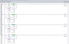
I wrote a program to monitor 4 inputs. and turn on outputs

1 - turn on relay 1 & 2
2 - Turn on Relays 3,4,5 & 6
3 - Turn on relays 7 & 8
4 - Turn on relays 9 & 10
5 - Run counter, turning on relays 1-10 (when 1 is on the rest are off)

switches 1-4 work great, when that part is the only one programmed
switch 5 work great, when that part is the only one programmed

but when the whole program is in, switches 1,2 & 3 do nothing
switch 4 only turns on relay 10

didn't test switch 5, because 5 wont matter if 1-4 don't work...

Questions are:

1. Why does a complete program STOP 1/2 of it from working
2. how to make this work.
3. as I only know how to make "main prog" is there a way to get main program to load and run other progs in the same PLC....thinking multiple smaller programs would work better then one big one...


if need be I can either upload the RSS, (rslogix) or screen shot my programs.

Thank you all!

Crossfire
 
here you go. Thank you

Correction:

Now none of the manual controls work (online mode shows the switches trigger, but no output)

but input 0/4 does start the seq program
 
Last edited:
The problem is the old double coil syndrome. What that means is that you used the same physical output address in more than one place in the program. Because of the double coil syndrome, the counter logic written below the switches logic is overriding the switch logic.
 
Last edited:
You need to combine your rungs so that you are not using the output addresses more than one time. Search the forum for "double coil syndrome."

Capture10.jpg
 
never thought of combining them like that!

I am going to try it. thank you


UPDATE: Did it that way, and works perfect!!!

BTW: this is going in my dodge ram! have Halo lights (headlights and fog lights) and will be for a "light show", turning the halos on and off in a circle...

oO Oo
o o

0123
4 5

6-9 are the "eyelashes" and "3 bulb strip" in the headlights (still working on what I want to do with them at the moment!

yeah got bored, what can I say!
 
Last edited:
It is probably not needed but you could also add a NO (XIC) I:0/4 instruction in front of each of the EQU branch instructions shown in Mark Timm's logic. That would block the counter's effect on the outputs unless switch 5 was on.
 
yeah, from what I can see, not needed, as I was the seq to be the override to the manuals, not the other way around!

and seeing that switch 5 when off resets counter to 0 and there is no EQU to 0, counter will not make a difference!
 
i hope so!!!

seriously though, because my understanding of the bits and files is minimal

so my B3:0/0 is one bit of one word
then my B3:0/1 is one bit of what? same word, or different word?

if the same word, then how do I goto next word
if different word, how do I use the other 15 bits of the word.

all I ever learned was to use a few inputs, and control a few outputs, very very basic.

I used a lot of google to do the S4, and counter and equals in my program!

sorry if I seem like a PITA, but I am coming from a PC/Programming background.

where the PC is live running a program to read/write digitals to parallel port.

this PLC is the first "disconnected" device I have worked on!

Thank you
 
'B3' is the 'bit' file
:0 is the first 16 bit word. You have 0 - 31
/0 is the first bit of that word. Each word has 0 - 15

B3:1/5 would be the sixth bit of the second word.

If you want to deal with all 16 bits in the word at once - for example to clear all of them - then you can just go up to the word reference. B3:1 is the second word. 'CLR B3:1' would set all 16 bits of that word to zero. Alternatively you can MOVe a word value into B3:x
 

Similar Topics

"Hello! Good day! Excuse me, I have a question regarding the 1761-NET-ENI. RSLinx has already detected it but it's not connecting to the PLC...
Replies
4
Views
129
Hi all, We have a very old pit pump system running on Micrologix 1000. Now, whenever there is an alarm for high conductivity, we want that alarm...
Replies
5
Views
1,256
Looking at a Micrologix 1000 1761-L32AWA, I tried to connect using the 1761-CBL-PM02 through a Serial to USB converter (This setup was used...
Replies
2
Views
985
Hello All I am trying to convert a ML1000 program for use in a ML1400. I didn't create the original program & documentation is non existent...
Replies
14
Views
4,409
Hey Folks, I have a customer with an older machine that is controlled with a MicroLogix 1000. The machine just quit working. The power light is...
Replies
22
Views
10,561
Back
Top Bottom