contact's reponse

medensat

Member
Join Date
Jul 2015
Location
CASABLANCA
Posts
19
Hello ,
I want feedback from the relay that controls the motor, in this relay there is a contact(RM1) that I'll use as input to the PLC that will inform me that the relay is on if I order. if the contact is opened the relay does not work, if it is closed the relay is on.
this is what I do:
if I press button Enable1 2second must wait for the motor to be running in the problem is that if the contact(RM1) is open the motor remains running
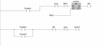
Capture.PNG
 
The first rung isn't workig. If it worked, M5 opens and the motor would not run.

Are you using a timer or a counter???
 
Hello,
First off lets make clear what it is you are tying to do and what material you are using to do it.

Is Enable 1 a "Maintained" or "NON-Maintained Switch"

When you say you want feed back from "a relay that controls a motor" and "In this relay thee is contact RM1"

1) Is this relay as you call it the actual "Contactor that is switching the Line power to the Motor?

2) Or is it a relay that is controlled by a PLC output and this relay is switching control power with operates the contactor that switches line power to the motor. (see where I am going with this?)

If you want feed back from a motor controller you want it to be from the contactor that is operating the motor, not the relay that is operating the contactor coil.

I am pretty sure this is what is happening in your case as you say RM1 is open but the motor remains on.
If you were getting feed back from a N/O contact on the motor controller then it would not/could not/should not be open when the motor is running.

Tell us a bit more about where this relay that has RM1 contacts in it is located in your circuit.
And give more detail about what it is exactly you wish to accomplish.

BCS
 
Last edited:
Hi,
i want feedback from the Contactor that is switching the Line power to the Motor , in this contactor there is a contact RM1(NO).
what i want to do is I'm going to start by pressing the Enable1 button (push button) i wait 2 second after I set the output to 1 (motor) the next cycle I will check if the contactor is closed so I'll test the contact state RM1, if the contact is closed the motor remains on, but if the contact is open the motor must not walk.
I have not understood is how early the RM1 contact is open but I have to control the contactor and the next cycle should be consulted RM1 touch if it was close.
 
If RM1 is an auxillary contact that is on the contactor that supplies line power to the motor....

Then how is it the motor is not starting through the closed contacts of the motor starter contactor....At the same time you are receiving feedback from the RM1 N/O auxillary contact.

Either you are leaving out a vital piece of information or you are misunderstanding how this works.

In you first post you say......

the problem is that if the contact(RM1) is open the motor remains running

And in post #4 I replied to you....

If you were getting feed back from a N/O contact on the motor controller then it would not/could not/should not be open when the motor is running.

So you see RM1 cannot be open at the same time the motor is actually running by your own description of the equipment you are using.
Yet your post say things that are contradicary to this.

Is there any other pieces to the puzzle (parts you are using) that you are not telling us about?

I am busy now but will try to post some things to help you if I get time today.

If you could please post a picture of your contactor with the RM1 aux contact and as much detail as possible (drawing, pictures, better explanation) this may help also.

If this is just a normal contactor with a N/O aux contact for feed back then you can do what you want to do....just not the way you are trying to do it.

Regards,
BCS
 
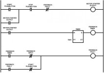
Ok here is what I think you are looking for.

You push Enable 1 (Start PB) if NOT stop or feed back fault then output motor 1.

If output motor 1 and NOT RM1 feedback then start timer.

If timer done then output M5 fault bit.

M5 fault bit will then unseal the Motor 1 Output and all operation is stopped.

(You can also parallel the M5 output with another output for a Fault Flasher Light or HMI indication of this fault taking place)
(You can also add a rung that if RM1 contact is closed then output to a "Motor is Running Indicator")

My software is a little different than yours, I don't have direct outputs off of timers, but this should give you an idea of what needs to be done and you can adapt this to your application.

Hopefully this was not homework, but if it is....sometimes it is more beneficial to be carried to the path instead of just having the way pointed out to you.

Good Luck,
BCS

EDIT: Bit Bucket beat me to it, and incorporated the fault output into the logic already. (y)
Also his N/C Stop button is more what you would see in a real world application, I was just trying to match what you already had going on so I used a N/O as you did.
Go with Bit Buckets Logic and you will be where you want to be.

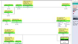
Feed Back.jpg
 
Last edited:
BCS:
Two things:
1) stick a preset value in your timer. With zero, you're gonna need a really fast contactor or a really slow PLC.

2) Your Feedback Fault bit is going to operate like a oneshot. it will still work, but will leave the scene of the crime and no evidence behind. So what stopped my motor? Was it a loose wire on the stop button or something else?

I would latch the fault bit or seal it in, and provide a manual means of resetting it.

I gottcha Okie,

The Preset was an over site, and I do get what you are saying about latch for the fault.

I was just trying point the OP in the right direction as he was walking in the total opposite direction of where the path is located.

Didn't get into Latches as he was using none and I don't know what software he is using. (just trying to keep it simple and give the OP something to work with in what little spare time I can mange while keeping the rungs small enough to screen shot the entire thing at once)

I agree with you 100% though and Bit Bucket put out a great example for the OP.

@ Bit Bucket -- What software are you using in your example?
That looks nice and clean to demonstrate from.

EDIT: Preset is corrected, thanks.
 
Last edited:
MS Paint, the goto tool for the cost consious engineer!

(I use it EVERY day :) )
 

Similar Topics

Hello , I want feedback from the relay that controls the motor, in this relay there is a contact(RM1) that I'll use as input to the PLC that will...
Replies
0
Views
1,040
I am stuck on fail ctrl error 1013 cannot get IP nor can do firmware update need help pls urgent
Replies
0
Views
170
Hi, I'm working with a Phoenix Contact FL NAT 2304-2GC-2SFP Ethernet switch, I already set the IP address and it has been working fine. I can...
Replies
2
Views
1,284
Hello all... I'm looking for a 480v 3ø 25+ amp Solid State Relay to replace a mechanical one beating itself to death keeping temp in a heating...
Replies
15
Views
1,961
Hi all, Historically i have used AB compactlogix exclusively working within the Logix/Studio5000 environment. I have decided to step out of my...
Replies
10
Views
1,881
Back
Top Bottom