Measuring water level in a tank

Well now you have been bamboozled by all the maths let's take it to a simple level (excuse the pun).
The sensor is a little above the bottom does it matter? you could just use an offset i.e. add the un-measured volume below the sensor if you want.
Calculate the volume in litres by measuring the tank ignoring the temperature & barometric pressure to display it in what ever units you want as it probably will not matter in your case.
Just a level then scale it from 0-100% (adding the bottom offset if you want).
Here is a simple calculator that will give you the required units based on the tank dimensions.
https://www.calculatorsoup.com/calculators/construction/tank.php
If you just want 0-100% and the level below the sensor is small or not really relevant then just start with an empty tank take the analogue reading and it should be 0 if you want to check just add water until you get some increase on the reading probably close enough for your purposes this is the min Raw.
Fill the tank to the upper level you consider full, note the analogue reading this is the max raw.
using the scale formula for example scaled min = 0 scaled max = 100 (%)
(((Scaled Max-Scaled Min)/(Max Raw Input-Min Raw Input))*(Raw Input-Min Raw Input))+Scaled Min = Scaled Value
If you want it in litres then calc the volume of the tank in litres and this becomes the scaled max.
 
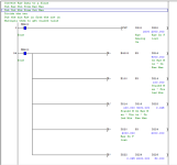
Mas01: here is some scaling logic it is using fixed values for the IN MAX, IN MIN, OUT MAX and OUT MIN, it converts the raw analogue input to a float to get more accuracy, then as the sum in the previous post converts it to the scaled value, by changing the fixed values for the in/out min & max you can match the expected values i.e. offset & spans. I have assumed 0 for both minimums and 4000 for max raw (depending on your analogue settings this could be 20000 for a Q AD card) and 100 as a percentage of the scaled value.
You could also change those fixed values for registers and have a set up screen on the HMI to calibrate them, I have not included for a divide by 0 error as the code contains fixed limits but if you change them to variables just in case the max out or max in are zero you will need to put compare in the divide rung of the logic to stop it faulting the PLC.
Also as I'm using floating point maths most of the registers are double so if you change the registers to ones not used in existing code you have you must make sure you use two for each floating point value for example All but the actual raw value (D200) all the rest are doubles so D220 to D216 are doubles i.e. D220 is D220 + D221 and so on.
If you do not need decimal points on the scaled value then just convert it back to an int [INT D226 D228] so D228 will contain 0-100% as an integer.
To change it from 0-100% to litres it is just a matter of changing the max out to say 1500 if the full level was 1500 litres.

Scaling code.png
 
Thanks for the replies thus far.
More info...I don't need to know the volume of the water, for me, that's neither here nor there. I just want a 0 to 100% falling/rising bar on the HMI PC screeno indicate how full it is. The tank is not a regular shape. It's a sort of L-shape (see picture I did on mobile phone). The overall height is about 6 ft. The pressure sensor is at the bottom of the deep end.

IMG_20201211_144748.jpg
 
Last edited:
Follow the advice given so far using a pressure sensor. The shape of the tank doesn't matter. The pressure at X depth is the same for say a smooth wall vertical tank as one that's shaped like an hour glass.

HTH
 
Follow the advice given so far using a pressure sensor. The shape of the tank doesn't matter. The pressure at X depth is the same for say a smooth wall vertical tank as one that's shaped like an hour glass.

HTH

The way I finally 'awoke' to this is when I realized that only the water directly over the pressure transducer inlet is exerting pressure on it.

If the inlet is 1/4" pipe then a cylinder of water about 1/4" in diameter is pressing down on the transducer. All the other water off to the side of that cylinder doesn't push into that fitting, whether the tank is square, circular, flat bottom, rounded bottom or conical shaped.
 
The way I finally 'awoke' to this is when I realized that only the water directly over the pressure transducer inlet is exerting pressure on it.


I'm not disagreeing, but what if the transducer's mechanical pressure element (e.g. diaphragm) is facing down?


P.S. it is important that the piping between the tank tap and the pressure transducer is full of water.
 
Last edited:
I'm not disagreeing, but what if the transducer's mechanical pressure element (e.g. diaphragm) is facing down?


P.S. it is important that the piping between the tank tap and the pressure transducer is full of water.

The way I see it is that it is the cylinder of water applying force into the port on the bottom of the tank.

If that goes through elbows, tees, tubing, etc the force remains the same. The pressure will push directly into the transducers element whether vertical, horizontal, angled, up or down.
 
The way I see it is that it is the cylinder of water applying force into the port on the bottom of the tank.

If that goes through elbows, tees, tubing, etc the force remains the same. The pressure will push directly into the transducers element whether vertical, horizontal, angled, up or down.


Code:
 |              |
 |--------------|          --------- Water level
 [COLOR=blue]|wwwwwwwwwwwwww|[/COLOR]              ^
 [COLOR=blue]|wwwwwwwwwwwwww|[/COLOR]              |
 [COLOR=blue]|wwwwwwwwwwwwww|[/COLOR]              a
 [COLOR=blue]|wwwwwwwwwwwwww|[/COLOR]              |
 [COLOR=blue]|wwwwwwwwwwwwww|[/COLOR]     P        v
 [COLOR=blue]|wwwwwwwwwwwwww|[/COLOR]    |[COLOR=Blue][B]-[/B][/COLOR]|   [COLOR=blue]---------- Pressure diaphragm[/COLOR] level
 [COLOR=blue]|wwwwwwwwwwwwww|[/COLOR]    [COLOR=blue]|w|[/COLOR]       ^
 [COLOR=blue]|wwwwwwwwwwwwww|[/COLOR]    [COLOR=blue]|w|[/COLOR]       |
 [COLOR=blue]|wwwwwwwwwwwwww|[/COLOR]    [COLOR=blue]|w|[/COLOR]       b
 [COLOR=blue]|wwwwwwwwwwwwww|[/COLOR]    [COLOR=blue]|w|[/COLOR]       |
 [COLOR=blue]|wwwwwwwwwwwwww|[/COLOR]____[COLOR=blue]|w|[/COLOR]       v
 [COLOR=blue]|wwwwwwwwwwwwww|[U]wwwwww[/U]|[/COLOR]   --------- Tap level
 [COLOR=blue]|wwwwwwwwwwwwww|[/COLOR]
 +--------------+
Just to be clear, if the tank and pressure tap are filled as above with |water|, then the Pressure sensor, P above, will measure the head [a], not the head [a+b]*.


* ignoring the atmospheric head
 
Mas01: here is some scaling logic it is using fixed values for the IN MAX, IN MIN, OUT MAX and OUT MIN, it converts the raw analogue input to a float to get more accuracy, then as the sum in the previous post converts it to the scaled value, by changing the fixed values for the in/out min & max you can match the expected values i.e. offset & spans. I have assumed 0 for both minimums and 4000 for max raw (depending on your analogue settings this could be 20000 for a Q AD card) and 100 as a percentage of the scaled value.
You could also change those fixed values for registers and have a set up screen on the HMI to calibrate them, I have not included for a divide by 0 error as the code contains fixed limits but if you change them to variables just in case the max out or max in are zero you will need to put compare in the divide rung of the logic to stop it faulting the PLC.
Also as I'm using floating point maths most of the registers are double so if you change the registers to ones not used in existing code you have you must make sure you use two for each floating point value for example All but the actual raw value (D200) all the rest are doubles so D220 to D216 are doubles i.e. D220 is D220 + D221 and so on.
If you do not need decimal points on the scaled value then just convert it back to an int [INT D226 D228] so D228 will contain 0-100% as an integer.
To change it from 0-100% to litres it is just a matter of changing the max out to say 1500 if the full level was 1500 litres.
Brilliant.
I'll try implementing this logic next week.
 
Just to be clear, if the tank and pressure tap are filled as above with |water|, then the Pressure sensor, P above, will measure the head [a], not the head [a+b]*

That follows, because the 1/4" column of water in the tube going up to the transducer is exerting its force down against the column in the tank, so a transducer at height will only read above its height.

I was presuming the transducer was at or below the bottom of the tank.
 
I was presuming the transducer was at or below the bottom of the tank.


yes, all that matters
  1. is the elevation difference between the water-air interface level
  2. and that the pressure tap piping is full of water
the location of the tap, and how the piping is routed, do not matter*.


* as long as it does not go more than about 34ft above the water-air interface.
 
Mas012 Replied: More info...I don't need to know the volume of the water, for me, that's neither here nor there. I just want a 0 to 100% falling/rising bar on the HMI PC screeno indicate how full it is. The tank is not a regular shape. It's a sort of L-shape (see picture I did on mobile phone). The overall height is about 6 ft. The pressure sensor is at the bottom of the deep end.
According to Mas01 last post I think the final few replies are irrelevant don't you think? All he want's to know is a rough level in the tank and possibly can control the level it fills to so as not to let it run dry but that code is probably already being done either by the existing pressure value or the new probes he has fitted.
 
[Update: most of these queries have been answered; our posts crossed]


Not at all tricky, but it could involve a fair bit of bookkeeping.

  • Is the pressure tap into the side of the tank?
    • Is it below any possible low level in the tank?
    • Is it on the outflow piping from the tank?
  • What is the elevation of the pressure gauge itself
  • Can the pressure gauge send a signal either to the PLC or to the HMI?
  • Is the water surface open to the atmosphere, or is the top of the tank under pressure?
    • If the latter,
      • Is there a measure of the air/gas/vapor pressure above the water,
      • OR
      • Does the pressure gauge near the bottom of the tank measure pressure difference between the lower tap and a tap at the top of the tank?
A sketch of the tank and pressure gauge would help.

The pressure sensor is mounted on a vertical rod inside the tank.
It's not below any low level on the tank.
The pressure reading already goes back to the PLC (bars unit)
Tank is open-topped.
Edit.... there's only 1 tap (faucet to you) used for filling the water tank in the first place. And a pump at the bottom of the tank to circulate the water.
 
Last edited:

Similar Topics

I try to find sensor for measuring ethanol in water in search engines. But there are little topics involve. Does anyone know which sensor can...
Replies
3
Views
5,098
Hi everyone, I don't know much of PLCs but it happened that i need to connect Leuze AMS358i Ethernet laser measurement to Productivity 1000...
Replies
0
Views
1,061
Hello everyone! Firstly I'd like to say that I'm new to this forum and also new to PLC programming world altogether, that said I really would...
Replies
27
Views
4,838
I am looking for a way to determine level in a silo. The material is called Perilite which has a very light density. Bulk density could be...
Replies
10
Views
2,748
Hello, I have an application where I need to measure the salt level/volume in a salt saturator. This is a fairly large tank where we load bulk...
Replies
21
Views
6,505
Back
Top Bottom