Micrologix 1400 Modbus problem

I just remembered something: the MicroLogix 1400 implements the Modbus TCP protocol over Integral Channel 1. So if pyModSlave or something similar can be set up to also communicate via Modbus TCP, then you could at least prove that you have the Modbus Master on the 1400 set up correctly, which we are pretty sure is already true. Success would point to the physical receiver side of Integral Channel 0's transceiver as the problem, and failure would point to a (subtle?) issue in your Modbus configuration.

Were you able to get anywhere with the 37h error code and that TechConnect article that @MikeyN mentioned?
 
Can you put a 'scope on the wires?

I mean, I am with @Ken Roach here: you have gone above and beyond with your due diligence; if only every thread included that level of detail!

Serial communication is digital, so it usually both very forgiving and either works or it doesn't without a lot of nuance, and there are not a lot of ways to mess it up (e.g. switching the A/B wires).

So I am as stumped as well, and grasping at straws seems like the only option left.
 
If you have Python on the pyModSlave end, it should be straightforward to bypass Modbus all the Modbus overhead and send characters to the 1400, and you could configure the 1400's Channel 0 as ASCII and use the ARD and ARL instructions to try to read them. That would be another way to test the receive side of the 1400's RS485 transceiver.

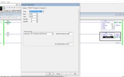
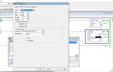
Btw, I noticed you have the [Channel Configuration] => [Channel 0 ]tab => [Prototcol control] => [Control Line] setting as No Handshaking (485 network). What happens if you change that to just No Handshaking i.e. without the (485 network) suffix? That is how I had my 1100 configured for Modbus Master recently, although I was ignoring the response.
 
That's usually the right question (that so OPs many fail to ask) and mindset that will get you to a solution, but I don't yet see what you are doing wrong.

  • The same two wires A/B are used for transmit and receive
    • the transmit to pyModSlave is working, because we can see the response message being sent from pyModSlave,
    • the transmit from pyModSlave is working, because it is received by the Click,
    • but is it possible the MicroLogix 1400 internals are broken and can transmit but not receive*?
      • Can you rewire/reconfigure for RS-232, either on the Channel 0 Mini-DIN or on Channel 2?
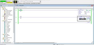
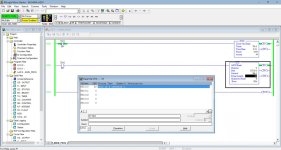
  • There is nothing else overwriting N7:0 (LAD 2 comprises the three rungs plus -(END)- rung shown).
  • There are two master instructions that would run 100ms apart if I:0.0/0 is 1, and the comms alone take ~15ms, but as long as I:0.0/0 is 0 it should not matter.
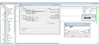
  • There is an Error Code of 37h (55 decimal) in the MG10:0 Setup Screen, but I did not find what that means; all of the published codes (cf. here) start with an 8h.
  • The timer should be sending a rising edge via that LIM instruction every third of a second or so, which should clear the MG10:0 error.
  • I did see a "Channel Status" block and related displays referenced in the MicroLogix 1400 reference manual; can you get some screenshots of those?
I have had very little trouble getting Modbus RTU working on my MicroLogix 1100 (RS232; if anything RS485 is easier), and you seem to be checking all the boxes; this must be very frustrating.

* Here's a thought: along the lines of the RS485 receive on the 1400 being the issue, can you connect RSLogix 500 via RS-485 on the 1400's Channel 0? Is that even possible (I only ever connected via RS-232)? It would take some shenanigans with RSLinx, but it would eliminate the Channel 0 receive side as a possible culprit.


I inserted the XIC I:0/0 to the second MSG command to disable it (nothing connected on I:0/0) I am using Rslogix Micro starter and I have it connected to the Micrologix using ethernet (channel 1) I reserved channel 2 (rs-232) for an HMI panel. The program is those three rungs only so its not possible that something is overwriting N7:0.


Mike
 
Do you have TechConnect? Article ID: QA2109 has quite a few things to check for error 37h, more than I am willing to type out here without risking getting in trouble. It is TechConnect access only though. Fortunately, I think you have already covered most of the answers they list.

I'm sure you have verified your node and channel. In the channel configuration, try setting your Pre Transmit Delay time to something higher than 1 ms. (perhaps 50 or higher?)


I don't, I am a home user learning this on my own. That is why I chose RSlogix Micro starter, it was a reasonable cost :)
 
If you have Python on the pyModSlave end, it should be straightforward to bypass Modbus all the Modbus overhead and send characters to the 1400, and you could configure the 1400's Channel 0 as ASCII and use the ARD and ARL instructions to try to read them. That would be another way to test the receive side of the 1400's RS485 transceiver.

Btw, I noticed you have the [Channel Configuration] => [Channel 0 ]tab => [Prototcol control] => [Control Line] setting as No Handshaking (485 network). What happens if you change that to just No Handshaking i.e. without the (485 network) suffix? That is how I had my 1100 configured for Modbus Master recently, although I was ignoring the response.


I can use channel 1 as serial and communicate with the ML1400 via a serial converter via rslogix so it would seem channel 1 is working properly?
 
If you have Python on the pyModSlave end, it should be straightforward to bypass Modbus all the Modbus overhead and send characters to the 1400, and you could configure the 1400's Channel 0 as ASCII and use the ARD and ARL instructions to try to read them. That would be another way to test the receive side of the 1400's RS485 transceiver.

Btw, I noticed you have the [Channel Configuration] => [Channel 0 ]tab => [Prototcol control] => [Control Line] setting as No Handshaking (485 network). What happens if you change that to just No Handshaking i.e. without the (485 network) suffix? That is how I had my 1100 configured for Modbus Master recently, although I was ignoring the response.


My understanding since I have the channel configured for 485 network that this is the proper choice. I did have it configured the other way, but that was before I discovered the wires were reversed. (the A/B markings on the adapter are wrong)
 
I appreciate all the responses, I am doing this to learn modbus communication and this sure has been a good lesson so far :)


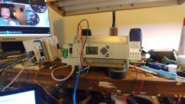
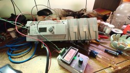
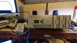
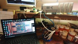
Attached is my setup. A little background. The Micrologix 1400 I am using I purchased used off Ebay a few months ago. Some of you may know that I built a model train layout using a Micrologix 1400 as a means to learn how to program PLC's. I saw this for a good price and bought it, the problem was I messed up and this model does not have the built in analog. I grabbed it as a means for a spare in case something happened to my train project PLC.


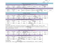
I may be doing a project at work in the future that involves communicating with a flow meter so I thought it would be a good idea to get some hands on with Modbus. I saw in another thread where someone mentioned inexpensive relay modules on Amazon that use modbus. I searched and found them. I bought that relay module, plus this temp/humidity module. So now I found a use for this PLC. (ah never know, might build another home project)


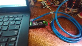
I purchased the 485 converter from plccable.com since it was cheaper then buying Rockwells's version. I have heard only good things about the aftermarket cables and parts from this site.


Now recently, another good deal came up on Ebay, this is correct Micrologix 1400 with the built in analog and it came with three modules, this is perfect as a spare unit for my train project since I have modules added on. ($700 BTW for the whole unit) I tested every input and output and even the analog and it works perfect. It was removed from a machine that a plant was closed and scrapping the equipment. (according to the listing) physically it is in great shape.


Now this means I have a means to test if the channel is bad on the micrologix, I will try the same program with this unit.


If this fails, it probably means the 485 converter I bought might be defective. I don't know if it is just a cable to terminals or are there any electronics inside to convert the signal.


I will report back what I find.


Mike

0427231834 (Medium).jpg 0427231835 (Medium).jpg XY-MD02 commands.JPG 0424231841 (Medium).jpg
 
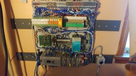
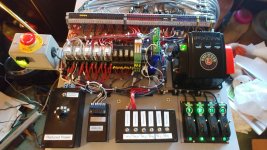
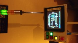
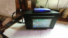
For what its worth, here are a few pictures of my model train PLC project, now in its permanent home as my around the ceiling layout in my living room. PLC is a Micrologix 1400, 6 inch HMI is a C-More Micro, a lot of the parts including the pedestal were taken from a place I used to work which closed and all the equipment was being scrapped. The panel with the Lionel transformer is my means to manually operate the layout when needed. I also had a 4 inch C=more micro panel which I had for a few years and was using it as a trainer to learn HMI. (back when I had a micrologix trainer unit) I decided to make it battery powered and using a wifi repeater, made it wireless so I can use it anywhere in my house. The PLC and HMI are integrated into my home network so I can also access the PLC and HMI from my computer to make changes and updates.


Crazy idea eh? :)

0316231821 (Medium).jpg 0316231822 (Medium).jpg 0322231922a (Medium).jpg 0322231924c (Medium).jpg 0325231609 (Medium).jpg
 
I can use channel 1 as serial and communicate with the ML1400 via a serial converter via rslogix so it would seem channel 1 is working properly?


Do you mean Channel 2? I thought channel 1 is the RJ45/Ethernet? See here.

Oh, and Channel 2 is RS232 only, not RS485; my mistake. Maybe you can run the MicroLogix Modbus Master on Channel 2, with a USB-RS232 converter on the pyModSlave end?

And isn't your USB-RS485 converter being used successfully with the Click when the laptop is running pyModSlave? That would suggest the converter is okay.

So Channel 0 is the 8-pin mini DIN RS232/RS485 port, and you got that 1400 as RFE from a plant. There is a warning in the MicroLogix documentation about not mixing the 1400's mini DIN-8 and some of the other MicrLogix (1200, 1000, 1500) mini DIN-8. Maybe the previous owners fried the receiver tri-state?

Have you tried sending a single character (i.e. not Modbus) from the laptop to the 1400's Channel 0 RS-485 configured for ASCII and using the ARD or ARL instruction to read it?
 
Another possible diagnostic:

Have the MicroLogix 1400 write a value to a Holding Register (Function Code 16 (0x10) Write Multiple Registers "3"xxxxx) instead of reading. That should work i.e. the holding register value should change in pyModSlave, even if the 1400 times out with an error because it does not see the response.

A rung with MOV S:4 N7:0 will use the 10kHz free-running clock's current value to write a different value from N7:0 each time.

Use XIO S:4/12 on the MSG instruction feed rung as the trigger (rising edge every 819.2ms).

If the Slave Node Address (dec) entry on the MSG Setup Screen has a value of 0, then the write is a broadcast so the 1400 will not expect a response and it should not trigger an error. I don't know how pyModSlave handles broadcasts, but the request should appear in the Bus Monitor Raw Data of pyModSlave.
 
Do you mean Channel 2? I thought channel 1 is the RJ45/Ethernet? See here.

Oh, and Channel 2 is RS232 only, not RS485; my mistake. Maybe you can run the MicroLogix Modbus Master on Channel 2, with a USB-RS232 converter on the pyModSlave end?

And isn't your USB-RS485 converter being used successfully with the Click when the laptop is running pyModSlave? That would suggest the converter is okay.

So Channel 0 is the 8-pin mini DIN RS232/RS485 port, and you got that 1400 as RFE from a plant. There is a warning in the MicroLogix documentation about not mixing the 1400's mini DIN-8 and some of the other MicrLogix (1200, 1000, 1500) mini DIN-8. Maybe the previous owners fried the receiver tri-state?

Have you tried sending a single character (i.e. not Modbus) from the laptop to the 1400's Channel 0 RS-485 configured for ASCII and using the ARD or ARL instruction to read it?


My mistake, I meant channel 0 The mini-din8. If I use a serial programming cable for channel 0, it is working. Unless the 485 part is different pins on the port.
 
Another possible diagnostic:

Have the MicroLogix 1400 write a value to a Holding Register (Function Code 16 (0x10) Write Multiple Registers "3"xxxxx) instead of reading. That should work i.e. the holding register value should change in pyModSlave, even if the 1400 times out with an error because it does not see the response.

A rung with MOV S:4 N7:0 will use the 10kHz free-running clock's current value to write a different value from N7:0 each time.

Use XIO S:4/12 on the MSG instruction feed rung as the trigger (rising edge every 819.2ms).

If the Slave Node Address (dec) entry on the MSG Setup Screen has a value of 0, then the write is a broadcast so the 1400 will not expect a response and it should not trigger an error. I don't know how pyModSlave handles broadcasts, but the request should appear in the Bus Monitor Raw Data of pyModSlave.


I will try that, but from my testing so far is the Micrologix is sending the correct data, but not seeing the response.


I will also try my other Micrologix 1400 unlikely two of them will have a bad channel 0.


Mike
 
Ok did some further testing with suggestions by drbitboy This will be several posts because I did several tests with screenshots.


First I changed the channel 0 configuration handshake to "no handshake" and communications broke down. The slave simulator saw no data at all. So that means the correct setting must be "No handshake 485 network"


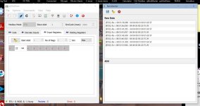
I do have a second Micrologix 1400 I connected it and set it up exactly the same as the other one (screenshots attached) the results were identical to the first ML1400. So this is starting to lean towards the 485 adapter (1763-NC01) I purchased from Plccable.com But I did further testing, see next post.

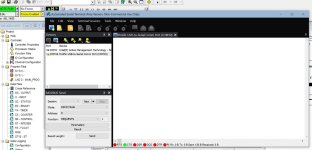
0430230842 (Medium).jpg bus monitor.jpg Channel Config.jpg Rslogix No data.jpg Rslogix Rungs.jpg
 
Next test was to change it to ASCII and try using ARD instruction and a serial cable connected to channel 0. The results were not exactly clean, but the string data does show what I typed on the terminal program. This was using a serial cable and not the 485 cable.

0430230954 (Medium).jpg ASCII Terminal.jpg rslogix ascii config.jpg Rslogix Ascii.jpg
 

Similar Topics

I have a spare Micrologix 1400 Series B I bought used on Ebay awhile back. I had thought of it as a spare PLC for my train project but I screwed...
Replies
4
Views
1,256
Good Day! Would anyone be able to explain what is happening with the COP's and MOV's in this Modbus poll routine? If anything I am confused by...
Replies
6
Views
1,732
I been tasked with setting up communication between a heating cooling unit manufactured by Advantage Engineering and a Microloagix 1400 plc. The...
Replies
6
Views
2,513
Hi, I am trying to communicate between a MicroLogix 1400 and a Click PLC. There is a great video from AD that shows the simplicity of...
Replies
2
Views
1,771
Hello everybody, I want to communicate with two PLCs (PC1: GE Fanuc: proficy machine edition which runs under quick panel IC754C & PLC2: Microlgix...
Replies
18
Views
5,018
Back
Top Bottom