Micrologix 1400 Modbus problem

mikeexplorer

Supporting Member
Join Date
Nov 2018
Location
Scranton,PA
Posts
179
I want to learn about modbus communication and I saw on another thread about inexpensive modbus relay units so I found it on Amazon along with a temperature and humidity module. I also bought the 1763-NC01 cable from plccable.com I have had no luck with the communication on the Micrologix.


I also have a Click PLC and I have been successful communicating with the modules with the Click, so I know the modules are good.


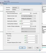
Using a bus monitor program, it appears the Micrologix is sending gibberish. I attached screenshots of the setup. Am I missing something with the programming and comm port setup?


Mike

bus monitor.jpg Comm settings.jpg Comm setup 2.jpg MSG setup.jpg MSG setup 2.jpg
 
In image [MSG Setup.jpg] for the the 15 0x0F Write Multiple Coils example, the Slave Node Address in the MSG Setup Screen is 0, and it should be 1. That said, 0 can used as a broadcast, so PyModSlave may receive it anyway, and since it is broadcast, the Modbus Master MSG instruction in the MicroLogix 1400 will not be expecting a response, which is why the "Message Done (DN)" bit has a value of 1, indicating success, i.e. the ML1400 put the ADU and PDU data on the wire like it was supposed to.

The Bus Monitor/Raw Data in image [bus monitor.jpg] shows PyModSlave receiving the correct number of bytes, 10, for the Write Multiple Coils command, every 5s:

  • 1 byte for the Modbus Slave adddress (i.e. should be a value of 1 - "Slave Node Address (dec)" in the MSG Setup screen)
  • 1 byte for the Function Code (should be 0x15 for Write Multiple Coils - "Modbus Command" in the MSG Setup Screen)
  • 2 bytes for the starting PDU address (should be 0x0000 to correspond to the Modbus Data Model address of 1 - "MB Data Address (1-65536)" in the MSG Setup Screen)
  • 2 bytes for the number of coils (should be 0x0008 - "Size In Elements" in the MSG Setup screen)
  • 1 byte for the protocol data Byte Count (should be 0x01 - 8 bits fit into one byte)
  • 1 byte for the protocol data (8 bits => 1 byte)
  • 2 bytes for the CRC.
The correct number of bytes being received says to me the baudrate and the 8N1 are correct on both ends. The odd values (lots of 0xFF, all bits have a value of 1, when most of the values should be closer to 0x00, all bits have a value of 0) suggest the sense of the bits on the wire are flipped (the UART on the PyModSlave side is making its best guess with the signals it is seeing), which I why I suggested swapping the A and B wires, assuming this is RS-485, which is likely if the 1763-NC01 is being used.

A terminating jumper between pins 5 and 6 of the 1763-NC01 terminal connector, if not present now, might also improve the situation, but I suspect that is more of an issue for a DH-485 network, and not RS-485 at 9600baud on a short cable.
 
Last edited:
The A/B data line labels really are always a coin flip: there is no vendor standard no matter who tries to make one.

I agree that the slave address in the MSG instruction needs to be "1", to match the address of the PyLogix slave.

When a serial frame has mostly 1's, I tend to think there's a data rate mismatch, like a "1" transmitted at 9600 baud is received as two "1"s if the receiver is set for 19200 baud. But the data rates all seem to match, here.

The captured serial data frame is:

Code:
E1 FF FF FF EF FD FF 81 4D FF

If you invert the bytes (just guessing about A/B inversion)

Code:
1E 00 00 00 EF 10 00 7E B2 00
That's a little closer but still gibberish.

The correct Modbus RTU serial frame to write eight False coils to Modbus RTU Slave 1 is:

Code:
01 0F 00 00 00 08 01 00 FE 95

Decoding Modbus by hand is do-able, but it's very easy to get stuff mixed up in your head for byte order or hex/decimal. There's an excellent tool from the good folks at Chipkin Automation that I use to decode modbus frames when I just want to do one:

https://store.chipkin.com/products/tools#modbus-rtu-parser
 
Last edited:
I did try flipping A-B around and it still shows gibberish, but inverted (screenshot attached)


I know what I have the bus monitor set for does not match the MSG statement but this was only a test. The slave still should have received the correct transmission even though it would have not responded since it was a mismatch.


I did these screenshots kinda in a hurry. I did do the test before with matching the slave to what the MSG command wanted (read/write a single coil) and it was still gibberish.


One of the screenshots in my first posts shows the channel settings for channel 0. Should be correct.


These devices I am using for testing work fine with the Click PLC and when I connected the click to the Bus monitor, I was seeing the correct data being sent to it.


Mike

bus monitor 2.jpg
 
ooh, that Chipkin has been mentioned quite a few times in the forum.

Since stating the obvious seems to work so well these days ;), another query for @mikeexplorer: do you have the grounds connected in parallel with the A-/A-/B+/B+ comm cables cf. https://www.plctalk.net/qanda/showthread.php?p=672037#post672037?


I tried attaching the ground to both sides it made no difference.


The wire is only about a foot long for testing, I am just doing this to learn modbus and try it out with some inexpensive hardware.
 
I did try flipping A-B around and it still shows gibberish, but inverted (screenshot attached)

That is not gibberish; that is valid Modbus protocol, both in the request (Rx) and the response (Tx). The CRC checks out 'nall (@Ken, can you confirm with the Chipkin tool?).

So the A-B wiring was the original problem; as @Ken said, that's a coin flip; the good part is that there are only two possibilities for the two wires if you know which two terminals are A and B on either end, and it is quicker to try them than to try to read the documentation.
 
Last edited:
Doooo yooooou speeeeak whaaaaale ?

Brian, that's some sweet annotation.

The second capture is exactly correct and consistent.

From the Chipkin Modbus RTU Parser:

Code:
Frame Analysis (01 01 00 00 00 08 3D CC)
--------------

The frame has no errors.

Poll Analysis
-------------
Device Address =1       =0x01
Function       =1       =0x01 =Read Coil Status
Point Address  =1       
Point Count    =8       

Frame Analysis (01 01 01 00 51 88)
--------------

The frame has no errors.

Response Analysis
-----------------
Device Address =1       =0x01
Function       =1       =0x01 =Read Coil Status
Point Address  =1       (Obtained from Poll)
Point Count    =8       (Obtained from Poll)
	Point Address  =1       State=0=Off
	Point Address  =2       State=0=Off
	Point Address  =3       State=0=Off
	Point Address  =4       State=0=Off
	Point Address  =5       State=0=Off
	Point Address  =6       State=0=Off
	Point Address  =7       State=0=Off
	Point Address  =8       State=0=Off

There is a correct response from the slave simulator, and no errors are logged.


But this capture shows a Modbus READ Coils command, not a WRITE coils command. So the zeroes in the simulator are being read into the MicroLogix.

Switch to a Write, of course, if you want to send data from the MicroLogix to the simulator.

The MSG logic, I assume, triggers the MSG every 5 seconds, since that's the timestamp interval.
 
Following the advice given here, I did discover that the wires needed to be reversed on the Micrologix side. I set up the Click PLC and the Micrologix side by side to read the temperature and humidity module I picked up. The click plc works fine so I took some screenshots of it and then worked with the micrologix. I now have the communication working properly (it seems) with the micrologix. Using the bus monitor set up exactly the same the transmitted data and received data match what the click was sending and receiving. The screenshots attachments are the micrologix only. It seems like I am down to the problem is I chose N7:0 to receive the data, but when I look at it, it shows zero. It should show 34 (22 hex) What am I doing wrong?

ML1400 Running.jpg ML1400 Temp Reading.JPG ML1400 Bus Monitor.jpg ML1400 No Data.JPG
 
Attached are the screenshots of the Click PLC which does work.


The modbus slave simulator is set the same as when I connect the micrologix, but I don't get the data back.


Mike

Click Software Running.JPG Click Read Temp.JPG Click Read Humidity.JPG Click Bus Monitor.jpg
 
... What am I doing wrong?
That's usually the right question (that so OPs many fail to ask) and mindset that will get you to a solution, but I don't yet see what you are doing wrong.

  • The same two wires A/B are used for transmit and receive
    • the transmit to pyModSlave is working, because we can see the response message being sent from pyModSlave,
    • the transmit from pyModSlave is working, because it is received by the Click,
    • but is it possible the MicroLogix 1400 internals are broken and can transmit but not receive*?
      • Can you rewire/reconfigure for RS-232, either on the Channel 0 Mini-DIN or on Channel 2?
  • There is nothing else overwriting N7:0 (LAD 2 comprises the three rungs plus -(END)- rung shown).
  • There are two master instructions that would run 100ms apart if I:0.0/0 is 1, and the comms alone take ~15ms, but as long as I:0.0/0 is 0 it should not matter.
  • There is an Error Code of 37h (55 decimal) in the MG10:0 Setup Screen, but I did not find what that means; all of the published codes (cf. here) start with an 8h.
  • The timer should be sending a rising edge via that LIM instruction every third of a second or so, which should clear the MG10:0 error.
  • I did see a "Channel Status" block and related displays referenced in the MicroLogix 1400 reference manual; can you get some screenshots of those?
I have had very little trouble getting Modbus RTU working on my MicroLogix 1100 (RS232; if anything RS485 is easier), and you seem to be checking all the boxes; this must be very frustrating.

* Here's a thought: along the lines of the RS485 receive on the 1400 being the issue, can you connect RSLogix 500 via RS-485 on the 1400's Channel 0? Is that even possible (I only ever connected via RS-232)? It would take some shenanigans with RSLinx, but it would eliminate the Channel 0 receive side as a possible culprit.
 
Do you have TechConnect? Article ID: QA2109 has quite a few things to check for error 37h, more than I am willing to type out here without risking getting in trouble. It is TechConnect access only though. Fortunately, I think you have already covered most of the answers they list.

I'm sure you have verified your node and channel. In the channel configuration, try setting your Pre Transmit Delay time to something higher than 1 ms. (perhaps 50 or higher?)
 
I appreciate very much that you're posting these careful and thorough screenshots, and hope that these are worthwhile lessons in serial troubleshooting.

The screenshots prove that the MicroLogix and the Click are both successfully polling the simulator, and receiving replies. If you look at the raw data for reading Modbus Input register 30002, they are exactly the same, byte-for-byte.

Yet the MicroLogix is apparently giving an error code indicating that it's not receiving a reply.

If this was RS-232, I would assume the Rx pin on the port is damaged or disconnected or mis-cabled.

But if it's RS-485, both pins are used for all transactions and it wouldn't transmit correctly if one was disconnected. You saw how reversed signals messed up the data communications when you started this effort.

That leaves me a little stumped. The data on the wire is provably exactly the same.

Modbus_Compare.png
 
Last edited:

Similar Topics

I have a spare Micrologix 1400 Series B I bought used on Ebay awhile back. I had thought of it as a spare PLC for my train project but I screwed...
Replies
4
Views
1,260
Good Day! Would anyone be able to explain what is happening with the COP's and MOV's in this Modbus poll routine? If anything I am confused by...
Replies
6
Views
1,732
I been tasked with setting up communication between a heating cooling unit manufactured by Advantage Engineering and a Microloagix 1400 plc. The...
Replies
6
Views
2,517
Hi, I am trying to communicate between a MicroLogix 1400 and a Click PLC. There is a great video from AD that shows the simplicity of...
Replies
2
Views
1,777
Hello everybody, I want to communicate with two PLCs (PC1: GE Fanuc: proficy machine edition which runs under quick panel IC754C & PLC2: Microlgix...
Replies
18
Views
5,030
Back
Top Bottom