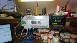
Micrologix 1400 Modbus problem

Another possible diagnostic:

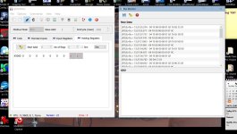
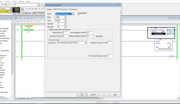
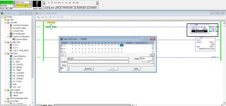
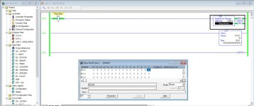
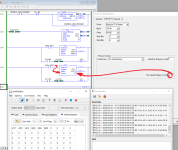
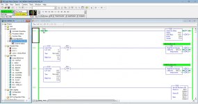
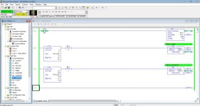
Have the MicroLogix 1400 write a value to a Holding Register (Function Code 16 (0x10) Write Multiple Registers "3"xxxxx) instead of reading. That should work i.e. the holding register value should change in pyModSlave, even if the 1400 times out with an error because it does not see the response.

A rung with MOV S:4 N7:0 will use the 10kHz free-running clock's current value to write a different value from N7:0 each time.

Use XIO S:4/12 on the MSG instruction feed rung as the trigger (rising edge every 819.2ms).

If the Slave Node Address (dec) entry on the MSG Setup Screen has a value of 0, then the write is a broadcast so the 1400 will not expect a response and it should not trigger an error. I don't know how pyModSlave handles broadcasts, but the request should appear in the Bus Monitor Raw Data of pyModSlave.


I did this test (screenshots attached) and this was successful, the slave monitor value changed as it ran.

bus monitor holding.jpg rslogix holding msg.jpg rslogix holding reg.jpg
 
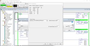
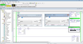
Ok This was another test and this is where it gets weird. I thought, why not flip this around? I also have the modbus master simulator so I configured channel 0 to be a modbus slave Again, screenshots attached. I used the master to simulate writing coils and this is using the 485 network including the 1763-NC01 cable.


This was somewhat unexpected, the ML1400 is reading values sent from the master simulator which would prove the 1763 cable is working since it receives data from the simulator.


Now this really doesn't make sense now. Why would it not be able to read data back when requested? (the temp/humidity module) I tried the real module and the slave simulator and everything seems good according to everyone who looked at the screenshots.


Mike

bus mon master setup.jpg rslogix slave chan setup.jpg rslogix slave data rec.jpg rslogix slave msg setup.jpg rslogix slave.jpg
 
Ok This was another test and this is where it gets weird. I thought, why not flip this around? I also have the modbus master simulator so I configured channel 0 to be a modbus slave
...
Now this really doesn't make sense now. Why would it not be able to read data back when requested?

Agreed, that makes no sense at all. If you read the Modbus RTU spec, there are timing issues i.e. there have to be so many character-times (3.5 or 1.5, IIRC) of delay between transmissions, and maybe that is not well-implemented on the Windows side.

But I can see your weird, and raise you a wacko:

I have been doing something similar. Here is the code of a Python script I am running:

try : serial.Serial
except: import serial

a=serial.Serial(port='COM3',baudrate=38400,parity='N',stopbits=1,timeout=4.0)

while True:
s=a.read(21) ### Read up to 21 bytes of a Modbus 16 (0x10) Write Holding Registers
L=len(s) ### Check the length of what was read
if 21!=L: print((L,s,)) ; continue ### If the length was not 21, print out the length and the bytes read and start another read
if b'\x01\x10\x00\x00\x00\x06'==s[:6]: ### If the 21 bytes were as expected ...
n=a.write(b'\x01\x10\x00\x00\x00\x06\x40\x0b') ### ... then reply with the appropriate response


What is happening there is that the MicroLogix 1100 is a Modbus Master, and the PC is listening on RS232 COM3 using the Python script above.

The 1100 is sending to Slave ID 1 (\x01) Modbus Write Holding Registers (\x10), starting at PDU address 0 (\x00\x00; i.e. Modbus "Address" [4]0001* for 6 registers (\x00\x06) messages at about 50Hz. This Python script is returning the correct response for Write Holding Registers, which response does not change because those four parameters do not change.

So while that script is far from an implementation of a Modbus Slave, the Modbus Master on the MicroLogix 1100 does not know the difference because the response is always the same.

I have been running that script for over two hours connected to the Modbus Master on the 1100, and it has been faultless: there was not a single request where the Python "Modbus Slave" script did not read exactly 21 bytes, and there was not a single case where the Modbus Master did not receive, and parse, a valid response (I have separate counters on the rising edges of the MGx:y/DN and MGx:1/ER bits).

* N.B. the [4] prefix is a convention and has nothing to do with the actual offset of the target address

So that is great, it is working as expected. Admittedly I am not checking the CRC, but I am consistently getting 21 bytes that start with that \x01\x10\x00\x00\x00\x06.

However, here is my wacko result: when I run pyModSlave on the PC listening to that same COM3, and leave the 1100 configured exactly as above, I get about

  • one in ten successful request/response transaction pairs, and
  • nine in ten that are
    • missing one complete request byte out of the 21,
    • and also typically have some flipped bits.
For those nine in ten, the CRC does not match and pyModSlave on the PC raises an error flag and does not send a response.

I dropped the baudrate from 38.4kbaud to 2400baud and got the same result.

I don't know what to make of all of this (@mikeexplorer's and my results), but I think another possible culprit is pyModSlave's and/or Windows 10's handling of the serial data. Pyinstaller did not work for me to make pyModSlave.exe, and I had to make some fixes just to get it to work under Windows 10 Python.

The attached files are

  • an annotated section of the pyModSlave Bus Monitor dump,
  • a screenshot of the MicroLogix code and a Bus Monitor dump from pyModSlave,
  • The MicroLogix Channel 0 configuration,
  • the pyModSlave Bus Monitor dump text file.

pyModSlave_Bus_Monitor_annotated.png MicroLogix_1100_Modbus_rungs.png MicroLogix_1100_Modbus_Channel_0_Configuration.png
 

Attachments

  • dump.txt
    2.9 KB · Views: 0
Last edited:
Thanks @MikeyN!

Changing Pre-Trasnmit Delay was mentioned by @MikeyN from that TechConnect article.

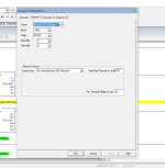
A delay of 20ms (50ms was also mentioned by @MikeyN and in the articles) makes quite a difference for my MicroLogix 1100 Modbus Master when communicating with pyModSlave.py in the normal way: no more errors! See below. Perhaps this will help the 1400s as well.
Pre-Transmit_delay.png
 
Excuse my ignorance, but pre-transmit delay is when the master waits 20mS after receipt of the last slave response before sending another poll?
 
Since the MicroLogix 1400 does Modbus Master stuff based on executions of the MSG instruction, there's no "poll list" or "inter-poll delay".


"Pre-Transmit Delay" is a minimum delay between when the controller switches from receiving to transmitting.

It is mostly important for auto-sensing RS485 converters like the 1761-Net-AIC, or for half-duplex radio modems. You use it in "485 Network (No Handshaking)" mode instead of hardware handshaking.

Typically it's most important when in Slave mode: the MicroLogix will wait that number of milliseconds after receiving a message before transmitting its response.

Inter-Character delay can be Modbus-specific. The Modbus standard says that 3.5 characters of idle time indicates the end of a packet, and putting a zero into that field means the MicroLogix 1400 will use that strict 3.5 character timing. Or, you can change it to a different integer number of milliseconds.
 
I can try changing the pretransmit delay and see what that does. Even if the modbus slave simulator was acting incorrectly, it still does not work when connected to the real hardware (temp/humidity sensor)


I also did try using a 8 channel relay board which uses separate modbus commands to read and write the relays. I can write to the device (close relays) but reading the relay status yields no results. I can post screenshots later today.
 
Might we inquire as to what actual device you are trying to communicate with the ML1400 over RS485?


Modbus is really easy, albeit, some don't follow protocol on development.
 
Might we inquire as to what actual device you are trying to communicate with the ML1400 over RS485?


Modbus is really easy, albeit, some don't follow protocol on development.


Modbus RTU RS485 SHT20 Temperature humidity transmitter Model XY-MD02.


The relay module is a Waveshare Modbus RTU Relay board.


Mike
 
I have tried a number of different MB simulators & what I did find is that I had to increase the request delays for example my FX3U with a none MB 232 card using my own version of MB code the delay after a recieve from a MB slave had to be increased to about 700ms, at first I thought it was my code or the FX 232 card was too slow, however, when I tried it on an old temperature controller I could reduce the delay before sending another request down to 50ms & it worked perfectly, I suspect the simulators combined with my programming IDE, Simulated HMI were making my laptop a bit slow on response, it seemed weird that I was getting the odd few chars (sometimes did not make sense).
I have not read all replies so perhaps the above is not what your problem is.
 
I have made some progress. I added a delay to the communication port 0 setup and now I am able to read the relays. Again, screenshots attached.


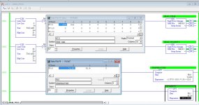
It also seems I can read the temp/humidity module now. The document for the module says it returns the data in Hex, so the first number is the temp in C, so I just have to do a calculation to convert it to Fahrenheit.


N7:1 is the humidity reading, not sure if the problem is because the data is in hex and N7:1 is a signed integer.


Mike

Comm 0 Setup.jpg Data Files.jpg Rslogix 1.jpg rslogix temp.jpg RSlogix Data Read.jpg
 
Hi Mike,

Cool beans, well done!

I don't know if you are intentionally reading the temperature and humidity in separate MSGs to get more experience with Modbus, but I thought I would mention that you can read them both with one MSG.

Also, I am not sure what you mean by the values being in hex; I understand the document displays the values in it's examples in hex, but Modbus RTU returns all of its values in binary, and except for the byte length, the slave ID, and the Function Code, all values in the protocol are unsigned 16-bit integers (nominally; see below) . What that means when reading data into an N-file on the 1400 in practice is that those same bits end up in signed 16-bit integers, so values from 0 through 32767 s will appear correctly, and values from 32768 through 65535 will look like -32768 through -1.

That said, each Modbus device manufacturer is free to define the meaning of the bits transferred, even splitting a single value across two or more registers if needed. For the XY-MD02, it does not matter for the humidity since the range is 0-100% and the range of valid values returned will be 0-1000, each increment of 1 representing 0.1‰, but for the temperature in degrees Celsius, which can be negative, the XY-MD02 returns values (0.1per increment) in twos complement, so the value in the N-file can be used as is.

Cf. items (I) and (vii) below.
 
I was following what the manual says about the module, I just assumed it required two MSG reads to get both values.


More success with adjusting the timeout values in the channel configuration. Once I made these changes, it read correctly and I added the calculation to convert the temperature reading from C to F. (Screenshots attached)


I want to thank you for your help, my intention was to learn how to use modbus and this was certainly a good lesson! I think that it didn't work at first was a good thing to figure out what went wrong. Hopefully I will get to apply what I learned.


Mike

rslogix chan 0 config relay.jpg rslogix temp and humidity.jpg
 
A quick look at the manual seems to indicate you can send a message function code X04 which instructs the unit to send the data continuosly.
 

Similar Topics

I have a spare Micrologix 1400 Series B I bought used on Ebay awhile back. I had thought of it as a spare PLC for my train project but I screwed...
Replies
4
Views
1,260
Good Day! Would anyone be able to explain what is happening with the COP's and MOV's in this Modbus poll routine? If anything I am confused by...
Replies
6
Views
1,732
I been tasked with setting up communication between a heating cooling unit manufactured by Advantage Engineering and a Microloagix 1400 plc. The...
Replies
6
Views
2,517
Hi, I am trying to communicate between a MicroLogix 1400 and a Click PLC. There is a great video from AD that shows the simplicity of...
Replies
2
Views
1,777
Hello everybody, I want to communicate with two PLCs (PC1: GE Fanuc: proficy machine edition which runs under quick panel IC754C & PLC2: Microlgix...
Replies
18
Views
5,024
Back
Top Bottom