Explanation of BTD nomenclature

Join Date
May 2011
Location
South Carolina
Posts
87
Good morning everyone.

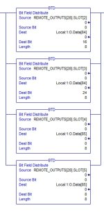
There are four BTD instructions in a program I am studying and I am confused on what part of the instruction means. See attached screen shot to see what my question refers to. I understand that the BTD is updating the Local outputs in groups of 8, but what does the [84] and [85] refer to after "Local:1:O.Data"? I have never seen that before. Thanks in advance.
BTD.jpg
 
Your slot data is 8 bits. Your Local:1:O.Data is a 32 bit Array of at least 86 words.

If you put your mouse over the Local tag it should open a information box to show the tag type and length. [84] is the 85th word in the array.
 
Last edited:
To really understand what is going on, you need to understand what type of I/O module you have plugged into Slot 1 of you Local chassis.

Understand that the BTDs are copying data in groups of 8 bits, not groups of 8 words. So the first BTD is manipulating addresses .Data[84].16 thru .Data[84].23, while the second is writing to .Data[84].24 to .Data[84].31.

What is in the 84th (or 85th, counting from 0) output data register of the I/O module will depend on what kind it is.
 
Last edited:
It's been a while since I set up a DeviceNet card, and there's a nifty tool that comes with Logix to make the mapping (somewhat) easier.

The trouble you're having is that each kind of DeviceNet device on your network has different amounts of Input and Output words that it requires. These are defined (IIRC) by the EDS files.

What the tool does is to allow you to select which devices you'll be reading in which order, and then it assigns the Data[] word that will be associated with that object.

It has a good/bad habit of trying to optimize. If you have a Gizmo that only needs 2 bytes of Input data, and then a Thingy that requires 4, it will put Gizmo in Data[x] bits 0-16, and Thingy split between Data[x].17-31 and Data[x+1].0-16. Even if the value in Thingy is a 32-bit value which really shouldn't be split.

Hence all those BTDs. They pack/unpack data because a MOV would be too easy.

You **CAN** make a manual map, and avoid some of the pain from the toolkit. I've done it, and its a PITA. But sometimes it's worth it.

Good luck
 
Since I am new to DeviceNet, how would I go about making a manual map to associate the inputs with the outputs? I have never used DeviceNet and will study up on it when I get through this.
 
It's been a long time for me and I don't have the software installed at the moment to play along, so I don't consciously know how -- I could just do it.

I **think** that what you do is open RSNetworks for DeviceNet and after either scanning all the devices on the network (if you have them; as an Integrator, we often don't get the actual I/O until after we're done coding), or manually entering their configuration (with the correct number of input and output bytes for each, which varies with how the devices are configured).

Then when you build the map in RSNetworks, there's a default option for to an automatic mapping, which you turn off, perhaps after having let it run once, just to give you a starting point.

Then you can double-click on the modules and can change its addresses to unused registers, which causes you to play games of musical chairs until things are where you want them.

You can leave holes (in case you think that this drive, which right now only needs 4 bytes in and 4 bytes out for status/command bits and speed setpoint/feedback, might possibly want to be configured to give you amperage or fault code or some other parameter, making it now 6 bytes of output. (Each device's block of data must be contiguous, so if you make a change to the configuration and didn't pad some unused registers, you'll need to move the device map to a different memory location.

If you really want more info from the Forum, you might want to start a new topic that is DeviceNet specific.

HTH, and good luck.
 
If you have a look around google or have a tech account, get the Knowledgebase "Getting results using the 1756-DNB and RSNetWorx for DeviceNet"
It explains what you need, also keep in mind when auto mapping devices to DeviceNet, some devices if setup by AB will map all the inputs/outputs and give all there parameter info, where devices that aren't AB licensed will need to be manual mapped so you need to do all the required parameters yourself.
I have done this, so anyone can do it, you just need to invest the time and read the above, or raise questions here, but there are varies threads you can also read which
 

Similar Topics

Hello all, A little background. Our organization is exploring using the Siemens S7 1500 PLCs in the future. We are an Allen Bradley's house...
Replies
16
Views
1,959
Good afternoon guys, hope y'all are doing well. Could someone explain how the wiring works on this card? From my research, each output is...
Replies
5
Views
2,276
Dear all, I am new to Allen Bradley PLCs and I have the following question. I want to know where to find a clear explanation of the register...
Replies
0
Views
1,081
Hello automation experts, I kindly ask your help about the pneumatic valve shown in the attached image. The valve is 3/2 which means it should...
Replies
9
Views
2,919
Hello experts, can you please help me understand the meaning of symbols shown in the attached pictures? First is U/S (I guess U represents...
Replies
6
Views
1,950
Back
Top Bottom