1762-if2of2 output wired to input different value

DwightA

Member
Join Date
May 2021
Location
Texas
Posts
4
I was trying to use a Micrologix 1100 and a 1762-if2of2 Analog IO card to demonstrate A/D and D/A conversion.

Simple ladder logic
Enter a value into one of the N7 (integer locations)
Move the value entered to the output
Output is hardwired back to input
Move from input into the next N7 location

I assumed (probably where the problem is) that the input would equal the output, but is doesn't?

Why is the input, not the same as the output?

Thanks
 
Looking at a program I have with that card, it appears that the scaling inputs and outputs should be the same when the inputs and outputs are set for Raw/Proportional data format and current signals. Then:
4mA = 6240
20mA = 31207

But I also believe that the default configuration for that card when you add one to your RSLogix 500 file will be to select 0 to +10vdc.

The 1762-IF4 has some switches on the card used to select voltage or current, the default being current. I am pretty sure those switches have to exist on the combo card as well. Are you using voltage or current signals?
 
The 1762-IF4 has some switches on the card used to select voltage or current, the default being current. I am pretty sure those switches have to exist on the combo card as well. Are you using voltage or current signals?

Yes the combo has the on/off switches as well
 
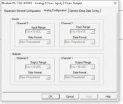
As far as I can tell, Input and output are scaled the same.

I wanted to move a value from an N value, out the output, back in the input, and moved to the next N value to demonstrate the entire process digital to analog and back to digital

Both Input and Output set for voltage
output 8 get 8 back, output 15000 get back 14520, output 30000 get back 29016

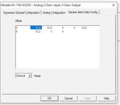
Capture.JPG Capture2.JPG Capture3.JPG
 
Both Input and Output set for voltage
output 8 get 8 back, output 15000 get back 14520, output 30000 get back 29016


Is 3% accuracy between two devices (DAC and ADC) totally unexpected?


"Typical Overall Accuracy" is 0.55% -20 to 65C; 0.3% at 25C, so those results are perhaps higher than advertised by a third to two-thirds of an order of magnitude.
 
Last edited:
If the dipswitches on your card are also set for voltage, and the results are 97% accurate, I'd say you have successfully demonstrated D/A and A/D conversion as well as one of the pitfalls.

Using voltage mode, how long are the wires and are they terminated well? Do you have a calibrator you can use to figure out whether it is the output or the input that is "off"?

Try your test with current signals and see if it is better.

Those cards I believe are 12 bit resolution and bit shifted left, so what you are seeing might be quite normal.
 
No real field wiring, just a short (<6in) jumper.
Measuring out with voltmeter. Output seems to be a little low.
I was assuming if the reference was off, Input and Output would have same error?
 
Note that your voltmeter will add a microscopic load, so don't leave it connected all the time.

Confirm that the dipswitches inside the card are set for voltage (this is not the default).
 
What I would do.... just to narrow down the issue

Put your voltage on your input, 0-10 and just move the input word to your output word and check with a meter that they are the same, if they are off then its your card if they are the same you have another issue

We make a lot of trainers and some have the IF2OF2 and the sample program we load to them to verify the I/O is just that, we have a 0-10vdc potentiometer and the output goes to a 0-10vdc meter, if everything is working correctly you can turn the pot to 1 and the meter is 1
 

Similar Topics

just re-uped membership so thanks for help previous and future. Bear with me on typing or responses back, pinky finger is broken and typing has...
Replies
5
Views
8,334
The MicroLogix manual states the Output Data File is from 0 to 32,760. My fluid Flow application calls for a control valve to open progressively...
Replies
2
Views
3,682
I have a Moog hydraulic servo valve that operates a cylinder that moves up and down. I have the 1762-if2of2 hooked up to it and sending the 4-20ma...
Replies
5
Views
2,628
Hi Sirs, Good Day. I have a simple questions/clarification regarding the connection of "negative channel" and "com" of the analog input module...
Replies
1
Views
1,727
Hey all, Been working on a little project using a Micrologic 1100, Just added this 2-in/2-out analog module (1762-If3Of2)to my project, and a...
Replies
4
Views
2,194
Back
Top Bottom