4 wire photoelectric sensor as Direct Logic 06 Koyo PLC input

JahrAlt

Member
Join Date
Nov 2022
Location
Morgantown
Posts
4
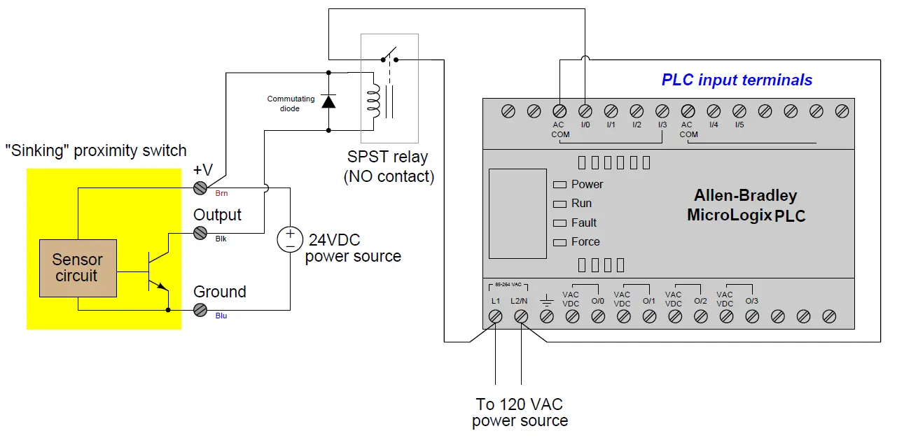
Hey, I am entirely new to PLC's and am trying to help my friend with a project. He wants to take the signal from a PNP photoelectric sensor as input. The sensor is lighting up and registering when it is blocked, but this does not register as input on the PLC. Any ideas?
 
It will depend on the PLC type input & sensor
PNP 4 wire sensors can have the following
+24v, -24v, Signal & the other wire can be many different things like N/O, N/C if tied to ov or + so it effectively changes it's mode.
Normally brown is +24, Blue is 0V & black is signsl out.
Again depending on the PLC the inputs can be NPN or PNP lets assume PNP i.e. a signal from a sensor is 0v when not sensed, +24v when sensed, very often the 0v of the power for the sensors needs to be connected to a terminal called SS, but it depends on the PLC input arrangement.
I suggest you download this manual
https://cdn.automationdirect.com/static/manuals/d006userm/ch2.pdf
 
thanks, yeah it has black,blue, brown, and white. I think I’ve correctly attatched photos of the terminals (on phone). The white wire is for determining Dark on or Light on, and we figured out how to switch between the 2. Still the problem is that it is not lighting up the input led on the plc no matter what we try. we have it plugged into the plc for its 24V power source… is that wrong to do? Is the signal not of a high enough voltage? It says that input is 90-120 V. No sign of an S/S terminal unless it goes by a different name.

C2CA6B83-25D3-4DA7-8F47-A63759C878FB.jpg 5D114274-D0AD-4955-8F17-68C6159A4A08.jpg 9E281BCA-4D7C-4999-8633-DE0A16C7A5CE.jpg 474FAD15-8804-48AE-B5E6-DDDE2010261A.jpg
 
According to your photo's you are not connected the 0V to the input OV, I assume this is C0, C1, C2 etc. I think these are the commons for the inputs in groups of 4.
 
According to your photo's you are not connected the 0V to the input OV, I assume this is C0, C1, C2 etc. I think these are the commons for the inputs in groups of 4.
+1

Input common has not been connected; even though the sensor supplies voltage at X3 when turned on, no current can flow.

Since sensor is PNP, C0 should be connected to the 0V of the DC power supplying the sensor. This will configure X0-X3 as sinking inputs.

See page 2-27 of the manual
 
The inputs on the D0-06AR are all 115 VAC. You are not going to have success connecting a DC sensor to it, regardless of whether the sensor is PNP or NPN.
Consider yourself fortunate. If you had tried to connect an AC sensor to a DC input you would have let some smoke out.
 
Yep I see it now, need new glasses lol, The op's only choices are get a 120v ac sensor or interposing relay then
 
Thanks everyone! So basically we will need a setup like I have pictured here?
instrumentationtools.com_programmable-logic-controller-plc.png
 
If it is a PNP sensor then you will be switching the Positive that goes to the relay coil, and the negative on the relay coil will need to be directly to the Negative on the power supply
 

Similar Topics

Does anyone have experience wiring this type of analog pressure transmitter up? It's 4 wires. 3 blacks and 1 green which I assume is earth...
Replies
9
Views
265
Hi everyone, I need some help I new with omron plc. I using plc CP1L. When I do the program it's good and the plc is function as program. But when...
Replies
1
Views
86
Hi there, Trying to get some ascii serial communications working via RS485 (COMMREQ functions). I have attached our wiring for the COM2...
Replies
1
Views
976
What's everyone use for I/O drawings on new installs. I am trying AutoCad Electrical, but can't download it due to a MS Office application running...
Replies
11
Views
1,312
I've been tasked with adding a 3-wire pressure differential transmitter to a system and drawing up the wiring to an existing PLC board. The...
Replies
7
Views
785
Back
Top Bottom