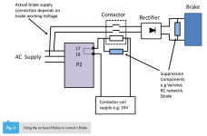
AC brake interference

I agree that the connection between the star points of motor windings and brake windings is unnecessary.
I am thinking that the unnecessary connection can cause current to flow between the output stage and line voltage (*). The drive possibly sees this as an earth fault.

*: Because the pulsed output is not 100% symmetrical over the 3 phases.
 
No, but tested out the motor etc & no issues identified.


Yes, 3p brake for sure. Existing installation, no obvious changes & the brake works ok electrically, as does the motor when the brake is manually released

So the brake star point hadn't accidentally been tied to the motor star point, it had never been removed when the VSD was installed lol
 
Wow
So many things on this.
No wonder you are having problems I am surprised you didn’t blow up the vfd

First the star point on the motor is normally never brought out in fact it is rarely available
Only a few manufactures bring it out .
Normal motor Line on 1,2,and 3
1- 4 Winding 1
2-5 Winding 2
3-6 Winding 3
High Voltage
7 - 10 Winding 4
8 – 11 Winding 5
9 – 12 Winding 6

High Voltage
winding 1 and 4 are in series
winding 2 and 5 are in series
winding 3 and 6 are in series

Low Voltage
4,5,6 are tied together (Star)
10,11,12 are tied together (Start) on most motors these are not available
So when you show the connection witch connection are you talking abut

I have run into this over 30 years ago where the brake was single voltage coli
230 v they would connect the motor leads 7,8,9 in the motor
That way if the motor was wired low voltage the brake would be powered from the low voltage line
And when the motor wired for high voltage the brake would still receive the low voltage
The motor winding would act like a transformer
The star point on all motor has zero volts on it it could be connected to natural or ground
A low voltage motor has 2 star points

You need to check all the wiring carefully to make sure it’s connected correctly
 
@GaryS.

Based on the photo of the name plate in post #8, I say that this is a bog-standard 3-phase asynchronous 4-pole motor. There are 3 windings, and depending on if you connect the windings in star or delta @50 Hz you can supply the motor up to 240V (in delta) or up to 440V (in star).

A photo of the terminal box on the motor will surely clear it up.
 
First the star point on the motor is normally never brought out in fact it is rarely available
Only a few manufactures bring it out .
Normal motor Line on 1,2,and 3
1- 4 Winding 1
2-5 Winding 2
3-6 Winding 3
High Voltage
7 - 10 Winding 4
8 – 11 Winding 5
9 – 12 Winding 6

High Voltage
winding 1 and 4 are in series
winding 2 and 5 are in series
winding 3 and 6 are in series

Low Voltage
4,5,6 are tied together (Star)
10,11,12 are tied together (Start) on most motors these are not available
So when you show the connection witch connection are you talking abut

I think the US does motor connections differently, at least to what I'm used to seeing. Strange to see this comment literally a few days after coming across an issue with a motor on an American machine that was wired as you've described. I was pretty confused to see no terminals and just nine loose cables in the box, what I'm used to seeing is this:

images


Incoming supply is connected to L1-3 and the terminal box contains copper links to configure as either star or delta, no other power connections are needed.

OP is Australian and a quick Google suggests their motors are wired the same way.
 
Haven't read the entire thread so I don't know if the age-old issue has been addressed:

"Programmable controllers, by the nature of their versatility, do not contain this suppression circuitry. The solution for this is quite simple. When a clutch/brake is used with a programmable controller, designers should include the suppression circuitry as needed in the wiring harness of the machine"

Craig

Brake suppression.PNG
 
Last edited:
Maybe you should have read the entire thread to see that his problem was with a 3 phase AC brake on a 3 phase motor and the star point of the brake and motor were connected together, which was causing a ground fault problem on the new VSD that he installed, to replace an old failed unit.
 
OP is Australian
:mad:


Wow
So many things on this.
No wonder you are having problems I am surprised you didn’t blow up the vfd
How so..?

First the star point on the motor is normally never brought out in fact it is rarely available
Strange, almost all motors through my 25+ years have always had a terminal block available with 6x studs for the windings.
They provide links to make the STAR/DELTA connections depending on the environment etc


You need to check all the wiring carefully to make sure it’s connected correctly
I did that & that is where the STAR point of the brake was connected to the same star point of the motor.


@GaryS.
Based on the photo of the name plate in post #8, I say that this is a bog-standard 3-phase asynchronous 4-pole motor. There are 3 windings, and depending on if you connect the windings in star or delta @50 Hz you can supply the motor up to 240V (in delta) or up to 440V (in star).

A photo of the terminal box on the motor will surely clear it up.
Correct, quite common down these ways. Although have also seen japanese motors that have the 6x terminals for single voltage.


Maybe you should have read the entire thread to see that his problem was with a 3 phase AC brake on a 3 phase motor and the star point of the brake and motor were connected together, which was causing a ground fault problem on the new VSD that he installed, to replace an old failed unit.
🍺🍺
Indeed.!


As an update, removing the brake star point from the motor star point has solved this issue.
Never ceases to amaze me what come across...
 
Very interesting lostcontrol. We have been in almost the exact same situation as you, though different models and our situation is intermittent. An application we've been doing for a decade is suddenly becoming an issue. 3 phase AC brake, intermittent ground fault detected. It has only been the last 6 months or so. I thought we had a ringer here, turns out our motors are separated in the way that solved the problem for you.
 
i've often seen different brands of VSD fault on motor short circuit or similar, only for the motor to test out & the problem to not repeat.
This instance, occurred each & every time until it was disabled. But disabling the earth fault just moved it to something else, in this case the DC link fault.

I guess the folks at ABB didn't have enough imagination to program in a "star point connected to some other energized source" fault 🙃 but if you think about how it likely detects a ground fault (I assume same concept as GFCI) it sorta makes sense that's the fault it threw instead. Current out ≠ current in. Usually that's because some portion of current out is leaking to ground but in this case must have been because some portion of the brake current (full voltage) was returning through the drive. After you disabled the ground fault it's still seeing this unexpected influx of current which is probably somewhat similar to what it sees during excess regen, so... "DC bus" fault I suppose is the next best way for it to describe what it's experiencing, even if the DC Bus voltage isn't above its threshold.
 

Similar Topics

We have an existing VSD where a three phase circuit breaker feeds the drive, and two phases also tee off to a contactor, which is energised to...
Replies
12
Views
1,490
Hey All, I've got a Vacon x4 VFD running in open-vector mode. It is spinning a heavy pin-mill wheel. It gets frequency reference from a PID...
Replies
20
Views
2,556
I have a old press brake that I want to retrofit a PLC to with a linear encoder on the Y axis and a stepper motor on X axis. Y Axis: I would...
Replies
11
Views
2,374
I need a little sanity check and hopefully advice from some experienced users. I have a mechanism that we're driving with a JVL MAC3000...
Replies
4
Views
1,141
Just curious how anyone else has controlled a VFD driven motor with a mechanical brake. I was using a PLC output to fire a brake relay while also...
Replies
19
Views
4,543
Back
Top Bottom