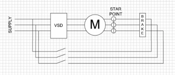
AC brake interference

Have you tested for any connection between the brake and the motor wiring?
No, but tested out the motor etc & no issues identified.

The star points haven't accidentally been tied together? Assuming 3Ø brake.
Yes, 3p brake for sure. Existing installation, no obvious changes & the brake works ok electrically, as does the motor when the brake is manually released
 
Can you post a wiring diagram of the motor and brake controls? I'm not quite ready to give up on the possibility of insufficient power to the brake coil when the drive and PLC are involved.
I dont have it on me, but they are definitely separate from the board. ( I can probably generate one though..)
however, this is a residential area so perhaps the voltage is dropped when both are energised.. (although this was a working installation before the VSD failed.)
So you point about both being energised at the same time is interesting.
 
A couple of observations.
That motor looks like it is fitted outside. You get an earth leakage fault, have you measured the insulation resistance?
On the high DC link error, this is normally created from regeneration where there is a mechanical load feeding back into the gearbox. Looking at the gearbox is that some kind of winding drum fitted? If it is lifting the load you have a positive load then the drive will work ok but when lowering, the load is negative and the drive cannot dissipate the energy sent back to the drive by the motor, causing the high DC link voltage. The drive will shut down to protect itself. A braking resistor is normally used to combat this problem

Some drives are better than others for controlling brakes, particularly if you are hoisting. Normal practice for controlling a brake motor from a drive is bring a seperate supply to power up the brake switched by a relay controlled by one of the drive outputs. There are normally additional setup requirements to control when the brake releases. If you need to ramp up and down then you can set a frequency threshold and also a current threshold for the drive to give a signal to release the brake Sometimes there is a contact on the relay. Sometimes the brake rectifier is fitted in the control panel, which reduces the wiring a bit.
 
A couple of observations.
That motor looks like it is fitted outside. You get an earth leakage fault, have you measured the insulation resistance?
Yes outside, but under a cover.
Tested insulation resitance, all tested out ok.

On the high DC link error, this is normally created from regeneration where there is a mechanical load feeding back into the gearbox. Looking at the gearbox is that some kind of winding drum fitted? If it is lifting the load you have a positive load then the drive will work ok but when lowering, the load is negative and the drive cannot dissipate the energy sent back to the drive by the motor, causing the high DC link voltage.
Yes, have experience with regenerative applications. In this instance though, the VSD can handle the load when the brake is manually released. This is for lifting & lowering.


To summarise:
  • The brake operators ok electrically
  • the VSD can control the load when the brake is released manually
  • the motor checks out ok & also operates ok when the brake is manually released
  • the VSD trips when the brake is electrically released & VSD started
  • the brake appears to be AC as opposed to the usual DC (that I am used to anyway)
  • I am confident that this is not a regenerative issue that requires a brake resistor to solve
 
I have encountered DC bus overvoltage faults before that actually had nothing to do with DC bus voltage and were instead caused by bad grounding IIRC. I think your drive was trying to tell you something before you disabled that trip, and it's still trying to tell you something even though you took the words out of its mouth. I don't think this has anything to do with regeneration or AC line voltage.

You said the motor was tested for insulation resistance; with what? A DMM? If so, that won't cut it. You need to check it with megger if you haven't already.

I suspect there is a path to ground (or to mains) from the VFD and through the brake. An unintention connection between brake circuit and motor circuit exists; you can confirm or refute this with a megger but whatever you do, don't say "I don't think that's the problem, because all that was working before we replaced the VFD" - because that VFD failed, quite possibly because of a ground fault that it lacked the fault handling to protect itself from.
 
Last edited:
I have encountered DC bus overvoltage faults before that actually had nothing to do with DC bus voltage
Interesting. I have come across motor short circuit faults before that test out ok..


I think your drive was trying to tell you something before you disabled that trip, and it's still trying to tell you something even though you took the words out of its mouth. I don't think this has anything to do with regeneration or AC line voltage.
Hmm, yes would agree with that. One thing that has not been tried is the manual release of brake with the fault enabled.

You said the motor was tested for insulation resistance; with what? A DMM?
An insulation resistance tester.. But, did not too the brake wiring for some stupid reason 🔨

I suspect there is a path to ground (or to mains) from the VFD and through the brake. An unintention connection between brake circuit and motor circuit exists; you can confirm or refute this with a megger
On the list to do..

but whatever you do, don't say "I don't think that's the problem, because all that was working before we replaced the VFD" -
No chance of that

because that VFD failed, quite possibly because of a ground fault that it lacked the fault handling to protect itself from.
very likely this..
 
Brake motors are not usually setup to ran off a VSD. Brake wiring off 1 leg and the star point is quiet common. Power up the brake or motor and check the voltage on the wires coming back on the circuit that is not live.
 
[*]I am confident that this is not a regenerative issue that requires a brake resistor to solve
[/LIST]

It may not be regenerative, but there could still be excessive current. This was not an identical replacement VSD? I would install the brake resistor just for troubleshooting purposes.

Is the incoming power Wye or Delta?

Do you have a high or low impedance ground?

Are you using a shielded VFD cable?

Have you tried any other drives?

Is the brake in good electrical condition?

I doubt there's a ground fault with the motor itself. New modern drives can detect that. Perhaps you could electrically disengage the brake and see if the voltage potential changes between the brake and the motor frame. Is there a leak there? Is the wiring that feeds the drive in good condition?

There's so many little things that can cause an issue like this that it's difficult to resolve without extensive and thorough troubleshooting, or a damn good guess and some luck.
 
From what you describe it sounds like you have some motor and brake leads crossed up
Try this

Manually release the brake and then run the VFD as if there is no brake, my guess you will get an output phase loss fault

The older VFD’s did not care they just sent a variable frequency out the new one actual have sensors that look at the output for the couteremf to see what happening in the motor any power in the output would be treated as motor generated power and passed into the DC Buss this would cause the buss over voltage fault that you are seeing you disabled the first fault that popped up leakage current that would normally detect this as a ground leak before the motor gets power from the vfd
This wiring problem may have been inadvertently done at the time of the original installation but the original vfd may not have been sanative to it. So it didn’t show up until you changed the vfd

I think you really need to recheck the wiring to both the vfd to motor and brake relay to the brake.
I would also recommend that you change the brake control from the plc to the vfd which is the standard today, try to fix bad installations when you can
 
Ok, so think I have identified the root cause.
Close investigation of the cable from the brake (and some testing) had 3x leads connected to the motor star point.

This sorta makes sense since it a 3phase coil & needs a common point.
As highlighted, modern inverters are more sensitive & monitor these things more closely, whereas this old original unit (and most likely its direct replacement) are not as sophisticated.

Will head back there tomorrow & remove the brake STAR point from the motor star point & re-test.
 
Why 3 leads from the same potential ?
1x from each phase, with the other side connected to the same STAR point of the motor.
previous model was a TECO 7300CV. Current model is ABB ACS380


Sorry, see images for before & after


If the 3x brake leads that are connected to the same motor STAR point are removed & connected together, that will remove the interference that the VSD is seeing.

acBrake.png acBrake2.JPG
 

Similar Topics

We have an existing VSD where a three phase circuit breaker feeds the drive, and two phases also tee off to a contactor, which is energised to...
Replies
12
Views
1,490
Hey All, I've got a Vacon x4 VFD running in open-vector mode. It is spinning a heavy pin-mill wheel. It gets frequency reference from a PID...
Replies
20
Views
2,556
I have a old press brake that I want to retrofit a PLC to with a linear encoder on the Y axis and a stepper motor on X axis. Y Axis: I would...
Replies
11
Views
2,374
I need a little sanity check and hopefully advice from some experienced users. I have a mechanism that we're driving with a JVL MAC3000...
Replies
4
Views
1,141
Just curious how anyone else has controlled a VFD driven motor with a mechanical brake. I was using a PLC output to fire a brake relay while also...
Replies
19
Views
4,543
Back
Top Bottom