Addresses needed for Micrologix 1400 built-in analogs

Here is my code

The file you posted has no analog expansion modules. If the processor is as you posted is a 1766-L32BXBA then the only analog inputs you have are embedded on the processor it self. See picture below for their addresses. Same as I posted in post #7 and Ron's #9

analogin.png
 
Maybe select the appropriate base so the stupid software knows what's going on???

johnmck66,

Here's how if you need help with that.
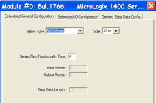
Under I/O configuration, select the processor and click on Adv Config.

You don't need to do this but it makes the data file I posted above look correct. The embedded analog inputs will still work without this step.

Check the Series/Rev/Functionality Type also. The file you posted says its a series B.

configure processor.png
 
Last edited:
Thanks a bundle to all you guys, it is looking like I have a better understanding of the addressing. I will try a routine in my processor for real tomorrow.
The last 15 years have been exclusively working on Siemens, so got rusty on Rockwell..Doh!
Cheers John M
 
On the controller itself:
Your digital inputs are I:0/0 through I:0/19
Your digital outputs are O:0/0 through O:0/11
Your analog inputs are I:0.4, I:0.5, I:0.6 and I:0.7
Your analog outputs are O:0.4 and O:0.5.

On the expansion I/O:
Digital Inputs are I:1/0 to I:1/15, I:2/0 to I:2/15, I:3/0 to I:3/15 and I:7/0 to 7/7
Digital Outputs are O:4/0 to O:4/15, O:5/0 to O: 5/15 and O:6/0 to 6/15

Hope this helps.

David
 
How about Micrologix 1000 Micrologix 1100 and expansion module?

Thanks, Wilkerson29847, for your detailed answer to my original post.
I'm currently working on replacing a Micrologix 1000 (now discontinued) with a Micrologix 1100 and expansion module.

Could you provide or tell me where to find similar I/O mapping information for those two controllers? I have not been able to find it.
 
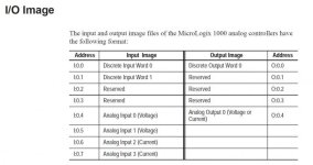
Found MicroLogix 1000 image file layout - still need for 1100

The User Manual 1000_1761-um003_-en p.pdf conveniently displays the information on page 5-2 under the heading I/O image. (See attached)

Unfortunately, no such REALLY HELPFUL table is in the MicroLogix 1100 manual.

Can someone please tell me how the I/O image files are mapped for the MicroLogix 1100?

MicroLogix 1000 IO Image files.jpg
 
Micrologix 1100 addresssing

Thanks, I did see that page. It's just not clear to me how to translate that to actual addresses. The nomenclature has to be very specific and it's been many years since I worked with it.
 

Similar Topics

Hello to all, Is it possible to export Codesys symbols to .txt, .csv or .xml in a similar manner like exporting symbol table in STEP 7? For...
Replies
0
Views
135
Hi guys, so I'm using BOOTP/DHCP tool in my virtual machine for setting up an IP addresses for basically everything. My only issue is always with...
Replies
3
Views
370
Hi. I'm doing an upgrade of an old 1400e to a new panel view plus 7 standard using ftv studio v 12,which will be communicating to a slc 5/04 via...
Replies
15
Views
2,634
Trying to find the proper documentation to explain the CC-Link Parameters for Mitsubishi remote I/O. The system I am modifying uses several...
Replies
0
Views
354
Besides using BootP in the past, I am relatively new to having to look for privately addressed devices in many control networks. All of the...
Replies
23
Views
3,974
Back
Top Bottom