Addressing in Rx3i PLC

IAR86

Member
Join Date
Apr 2024
Location
Glasgow
Posts
8
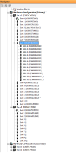
I have a system using Rx3I CRU320 redundant CPU with Proficy Machine Edition Software. In the hardware configuration of each CPU module, under transfer list tab, following is configured on both PLC.

%I Reference: %I00001
%I Length: 4
%AI Reference: %AI00001
%AI Length: 4

I think this is incorrect and I need to update.

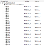
When I look at the address of IO card channels, it is given as "Rack.slot.channel" format (eg %IW0.8.0.1 for 1st channel of AI card in slot 8). I was expecting address something like %AI0001 so that its easy to understand whether its shared between PLC using transfer list configuration.

Can someone explain how to identify the address and length to be configured in the transfer list?
 
What version of Machine Edition?
I just added (offline) an ALG608 module to an existing target and version 9.5 assigned it an %AI address. I've never seen the rack.slot.channel format in a GE PLC. Are you looking at the hardware configuration for the module or in the variable table?
 
What version of Machine Edition?
I just added (offline) an ALG608 module to an existing target and version 9.5 assigned it an %AI address. I've never seen the rack.slot.channel format in a GE PLC. Are you looking at the hardware configuration for the module or in the variable table?
Hi Steve, Thanks for response. I am using Machine edition 9.0. I am looking at the hardware configuration. please see image attached.
 

Attachments

  • Untitled.png
    Untitled.png
    16.6 KB · Views: 9
Will it accept a %AIxxxx address instead of TEST1 in the variable field?
If I enter %AI0001 in the inspector window for TEST1, it is accepted. but when i checked in the hardware config, TEST1 variable is removed from channel IW1. when I double click IW1 and select TEST1 variable, address is changed again to %IW0.14.0.1.
If you mean whether I can assign address %AI0001 to channel IW1? No I cannot assign the address.
 
The screen shot looks like what I see when I add a module to to View Control target rather than a PLC target. Can you provide an overview of the complete system architecture?
Hi Steve,
sorry I am very much familiar with Proficy machine edition software. I have attached the screenshot of hardware config. We have two CPUs in hot standby redundancy mode.
 

Attachments

  • Hardware config.png
    Hardware config.png
    27.7 KB · Views: 6
If you open the Inspector, click on Hardware Configuration and change the Default Variable Mode from False to True, I/O Variables are enabled.
When enabled, the addresses are coupled to the hardware. This is what gives the rack.slot.channel addresses.
 
If you open the Inspector, click on Hardware Configuration and change the Default Variable Mode from False to True, I/O Variables are enabled.
When enabled, the addresses are coupled to the hardware. This is what gives the rack.slot.channel addresses.
Thanks dYost. With "default variable mode" set to false and adding a new module, I can see the address is shown normal as %AI00001.
With default variable mode set to true, can I use the transfer list tab in hardware config to share the variables between two CPUs?
how to determine the address start and length for the transfer list configuration if the address is displayed rack.slot.channel addresses.
 
It seems that the transfer list tab in the hardware config is used only for CPU memory segments. I see that if variable mode property is set to true for a module (which is true in my software), then Input/output transfer list has be set to true for each variable individually in the inspector window.
 
Why would you want to use rack.slot.channel addresses (I/O variables)?

From Machine Edition companion...

********************************************
Hardware Configuration Node Properties
These properties apply only to PACSystems or VersaMax controller rack systems.

Default Variable Mode​

(PACSystems targets only.) The default setting of the Variable Mode property of every new module or Genius bus added to a PACSystems target. Existing modules and Genius busses are unaffected.

Choices:
  • True: Enables I/O variables for every new module or Genius bus added from now on to the target, unless the module does not support I/O variables. In the latter case, the module's Variable Mode property is set to False and is read-only.
  • False: (Default.) Disables I/O variables for every new module or Genius bus added from now on to the target.
You can still enable or disable I/O variables for a particular module or Genius bus.
********************************************
 
Last edited:
Why would you want to use rack.slot.channel addresses (I/O variables)?

From Machine Edition companion...

********************************************
Hardware Configuration Node Properties
These properties apply only to PACSystems or VersaMax controller rack systems.

Default Variable Mode​

(PACSystems targets only.) The default setting of the Variable Mode property of every new module or Genius bus added to a PACSystems target. Existing modules and Genius busses are unaffected.

Choices:
  • True: Enables I/O variables for every new module or Genius bus added from now on to the target, unless the module does not support I/O variables. In the latter case, the module's Variable Mode property is set to False and is read-only.
  • False: (Default.) Disables I/O variables for every new module or Genius bus added from now on to the target.
You can still enable or disable I/O variables for a particular module or Genius bus.
********************************************
Hi NetNathan,
This is existing software in the client site which uses rack.slot.channel address. To resolve some of the existing issues, I needed to review and update the transfer list (from bumpless PLC Changeover) and to add module for new instruments. I wanted to understand on how to configure transfer list tab in hardware configuration. I understand now that with rack.slot.channel address, I need to set the transfer list property on individual variable rather than using tansfer list tab. The transfer list tab in hardware config is useful only to transfer CPU memory segments. In my case, I am using I/O variables.
 

Similar Topics

I am very new to Modbus and the industry, so forgive me if I am missing something obvious. I have known Modbus register addresses coming from a...
Replies
7
Views
238
See the screenshot of EIP tag list. We are trying to read in a digital input that is hard-wired. It is shown here as I31.1. I believe we cannot...
Replies
7
Views
286
Hello all. I have a Simatic SM374 (374-sxh01-0aa0) sim module. I am using TIA portal v.18. I can't find this module in my list of hardware devices...
Replies
12
Views
763
Hello, I have a device with 68 words input. But one block on the Devicenet Scanner is only 61 words. I am trying to map this device to 2...
Replies
3
Views
536
We had an AC 800M stand alone controller fail. We have a spare, and we are trying to set it up on the bench. We can connect with the serial cable...
Replies
0
Views
313
Back
Top Bottom