analog input overcurrent protection

stern

Member
Join Date
Apr 2013
Location
Saint-Petersburg
Posts
4
Hello,

I have 4-20mA 2-wire transducers powered using external power supply (passive analog module inputs).
How can I protect PLC inputs from short circuit at sensor side?

As stated in manual the max input current (destruction limit) is 40 mA, input impedance 250 Ohm.

Thanks.
 
I'm not sure what "protect PLC inputs at the sensor side" means.

I think you mean that the analog outputs are passive analog 'outputs', don't you, because passive 4-20mA outputs need an external power supply. If the 24V+ shorts to its return, the voltage drops to near zero so the danger is potentially overheated wire insulation from high current, not damage to the AI.

I've seen some people fuse the +24V line from the power supply to the transmitter, although many power supplies have crowbar over-protection circuit nowadays.

If the loop shorts to ground (24V return) between the transmitter and the PLC AI, the transmitter will regulate the current in the loop (it doesn't know that the AI is bypassed). The PLC won't get a good signal, but there's no danger of overheating or damage to the AI.

Maybe I'm missing some failure mode here. Something in particular?
 
I have 4-20mA 2-wire transducers powered using external power supply (passive analog module inputs).
How can I protect PLC inputs from short circuit at sensor side?

Stern,

Sounds like you have the opportunity for a wire to be shorted or an event to occur where you can damage your AI. I would consider your AI as sinking and not really passive. I have had troubles once with some RA Flex IO. Problem wasn't the IO, it was the device wiring was installed laying in open trays and parts were dropping on the wiring, crushing/damaging the wires, and causing shorts in the circuit.
Our solution:

1. Open ended wire ways, conduit, & shielding in those 'drop zones' to protect the wires

2. 500mA fuses to protect with LED indication on each of the AI before the signal into the PLC.

The customer is extremely happy. Now if a short occurs their electricians can find the wire readily via the LED indicator, and they are not taking out blocks of AI from 'over heating'.

"Most active instruments have passive pickups and an active preamp in the control cavity" - if the vendor told you this was a passive module then it probably is, but I would consider sinking & sourcing when you talk about IO. Helps me with my understanding.

Best Regards.
 
Sorry for my english.

Yes, I mean I have sinking AI card and use external power to supply 2-wire transducers.
So when field shorts occure AI channels'll blow up as a result of overheating.

I make all my field analog connections through a fused terminal block like this:
I don't think this is a good idea.

Fuses with low rated current are highly resistant. For example, cold resistance of 32mA fuse is about 262 Ohm. Add it to AI channel resistance 250 Ohm. When 24V drops at AI channel, current will be about 1.5 fuse rated current. So fuse'll blow up min. after 1 hour.

Maybe your AI cards have less impedance?
 
Last edited:
Maybe your AI cards have less impedance?


The miniture fuse blocks are convenient and the fuse selection needs to match up to what you are working with. I called a friend...I have to correct my fuse rating to 1/10 & 1/8A - 125mA are what they are using now.


"When a circuit is driven with direct current (DC), there is no distinction between impedance and resistance; the latter can be thought of as impedance with zero phase angle." -Wikipedia


A 250 Ohm shunt resister is typically installed to allow the receiving device to "read" or "see" the voltage drop (4-20mA signal). Been a standard with Analog signals for some time...there are plenty of members here who can explain that better than me.


Please look through these and consider, they've helped my understanding:

http://www.plctalk.net/qanda/showthread.php?t=67789&highlight=4-20mA+chart

http://www.plctalk.net/qanda/showpost.php?p=236458&postcount=11


**Do you want to protect the PLC or don't you?**


If you do then you should install "field analog connections through a fused terminal block", or fuse them some other way. Install the fuses you calculate to protect the system.

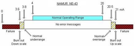
I found this 4-20mA Scale here, I apologize I haven't found the original post. Just to provoke some thought.

4-20mA Operating Scale.jpg
 
Sorry for my english.

I don't think this is a good idea.

Fuses with low rated current are highly resistant. For example, cold resistance of 32mA fuse is about 262 Ohm. Add it to AI channel resistance 250 Ohm. When 24V drops at AI channel, current will be about 1.5 fuse rated current. So fuse'll blow up min. after 1 hour.

Maybe your AI cards have less impedance?

You can select the fuses to minimize this. There are fast blow fuses in various mA ratings.
 
You can select the fuses to minimize this. There are fast blow fuses in various mA ratings.
But it is fast-acting. To be realy fast current must be >2.75In.
fuse.jpg

It seems to me fuse protection is unreliable for 250 Ohm AI cards.

In any case I haven't found more fast or less resistant fuses.
If you know ones, will be grateful for information.

Maybe there are any miniature circuit breakers for such ratings?
 
First off, I'm not sure what the impedance of the AI has to do with anything. Your card specs should identify the max allowable current.

Second, you can only do what you can do. I doubt if you will find a breaker faster than a fuse. My experience is that a fast blow worked fine. I think we used 100 mA fuses, but I'm not 100% sure. They could have been 1/2 A.

Third, the blowing of a fuse and the damage to your card are both dictated by heat generation. In a severe dead bolt short you will blow the fuse faster than the 275% spec above.
 
+1 again for Tom!

First off, I'm not sure what the impedance of the AI has to do with anything. Your card specs should identify the max allowable current.

Second, you can only do what you can do. I doubt if you will find a breaker faster than a fuse. My experience is that a fast blow worked fine. I think we used 100 mA fuses, but I'm not 100% sure. They could have been 1/2 A.

Third, the blowing of a fuse and the damage to your card are both dictated by heat generation. In a severe dead bolt short you will blow the fuse faster than the 275% spec above.

Stern can ask two questions:
What do I need for fuse protection?
you've been given some great options here; simple as they are

What is the 250 Ohm Impedance/Resistance used in an Analog Circuit?
There are some great posts on the forum that can help...use the general search tab and dig in. Use the references

A 250 Ohm shunt resister is typically installed to allow the receiving device to "read" or "see" the voltage drop (4-20mA signal). Been a standard with Analog signals for some time...there are plenty of members here who can explain that better than me.

Best Regards Stern
 
But it is fast-acting. To be really fast current must be >2.75In.
View attachment 26759

It seems to me fuse protection is unreliable for 250 Ohm AI cards.
24V shorted across 250 ohms drives 96mA through the resistor (0.096A = 24V/250ohms) and dissipates 2.3W (24V^2/250ohms = 2.3W)

With a fuse in series with a 262 ohm resistance, the loop resistance increases to 512 ohms.
24V shorted across 512 ohms drives 47mA through the resistor (0.047A = 24V/512ohms) and dissipates 1.13W (24V^2/512ohms = 1.13W)

Both 47mA and 96mA fault currents do exceed the analog input limitation spec, which doesn't state a time duration.

Both fault currents fall into the fuse's 32-100mA range, so the fuse reaction time is 0.10 to 0.5 seconds, according to the table.

I wonder if the spec isn't assuming a continuous 40mA that would damage a 1/10W input resistor.
 

Similar Topics

I'm having trouble calming down 2 Tempo Sonics. I'm using Studio 5000 CompactLogix my Raw value is jumping around from 8575.0 to 8755.0 at a...
Replies
30
Views
1,146
I cannot add SLC500 analog input tag (I: 8.3) to EZSeries Touch Panel Editor (V 5.3). I used all the listed tag datatype but it all says "Invalid...
Replies
10
Views
260
Hi, I have questions. I have Analog Input that need to put into Ignition Designer. But I don't know how to put?
Replies
1
Views
120
Omron AD081-V1 Analog Input Card Offset & Gain Adjustment Entering Adjustment Mode 1. Set the input card in adjustment mode (Turn ON Dip SW No-1)...
Replies
0
Views
88
Why AMIo800 Analog input module's I/O LED is Lighting up Red? Checked module connections, 4-20ma wires etc but this light is continuously Lighting...
Replies
1
Views
112
Back
Top Bottom