Building a download cable for QPJ2D100L2P HMI

david90

Member
Join Date
Apr 2010
Location
ca
Posts
202
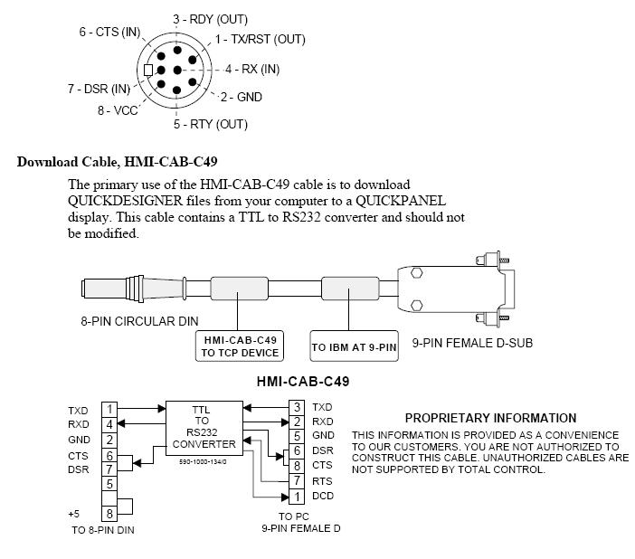
The download comm cable that I'm trying to build is vaguely depicted below. I could buy the cable but it's expensive and I wish to learn more about rs232 comm.

What is the reason for connecting CTS and DSR lines together and what does that say about how the HMI control data flow? I have been reading on hardware flow control which uses RTS and CTS line but I still can't make sense of the block diagram below. Does the block diagram indicates that the the comm link between the PC and HMI is synchronous or asynchronous? Also I have a feeling that the block diagram is incomplete and is not showing all connections.
profac10.jpg
 
Last edited:
This is probably no the best choice to train yourself on RS232 serial communications. That box labeled "TTL to RS232 Converter" is a chip in the cable that converts the 5 volt signal level on the Quick Panel side to the 12 volt RS232 signal level. It's not just a matter of identifying which pin on the 8-pin DIN to connect to its counterpart on the 9-pin Dsub.
 
I'm aware that this cable include circuitry to convert TTL to RS232. I have worked with the MAX232 IC TTL to RS232 converter before so I do have some experience. Plus I think it will be a good learning experience. Up to this point, I have only worked with asynchronous communcation (3 wires: rx,tx,gnd).

Currently I'm just trying to make sense of the flow control lines. I think the dsub pin 7 is level shifted and connected to pin 6 and 7 of the 8pin DIN. Can someone comment on this?

If a pair of devices use hardware flow control, then does it means that their comm baud rate doesn't need to match?
 
Last edited:
I recently did a project that was modifying the following old panel:

Total Control Products with the following numbers:

QPI21100C2P Series A

QPI-ADB-201 comm module for DH+

Download cable: HMI-CAB-C49 (May be included with the package below)

We bought the above cable from GE. There was an old one in the cabibet too. These were later revisions and looked different from the above picture. Neither one had any of the "bumps" shown in the middle. Just looking casually at them, they look NO different from many other serial cables. They worked. I didn't take apart on of the cnnectors to see if there is any electronics in there.
 

Similar Topics

Hello everyone, I am a student and would like to take the next step and learn FactoryTalk (Batch preferably) and how to create HMIs etc. Would...
Replies
4
Views
496
Hi all Trend seemed to have carved a niche in building controls. The controllers seem expensive and inflexible, in the words of a Trend user. Do...
Replies
1
Views
493
I have a 24" plotter that we print out full scale backpanels and transfer all the holes to a backpanel for faster layout and build time. Does...
Replies
11
Views
1,635
Anyone building cabinets according to Korean standards? What to think about? Do you need to use components with Korean approvals?
Replies
0
Views
839
General question for everyone. I'm finishing up some industrial electrician training in the next couple years and then plan to open up my own shop...
Replies
2
Views
1,568
Back
Top Bottom