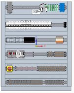
Building panels faster.

JeffKiper

Lifetime Supporting Member + Moderator
Join Date
Jun 2006
Location
Indiana
Posts
2,460
I have a 24" plotter that we print out full scale backpanels and transfer all the holes to a backpanel for faster layout and build time.
Does anyone else do this or something else to speed up panel builds?
 
The company I worked for started to do this in the late 80's early 90's, however, the cad system was unix based with A3 plotter we would tape the sheets together initially, it some time in getting the exact dimensions correct but from that point on it worked pretty well, This process seemed to be abandoned in the late 90's when we moved to PC's & things like Autocad, however, we still produced the layout drawings but it was upto the panel men to lay out the parts.
 
I do this. We have a roll-fed 36" wide plotter. The only time I have to tape them together is when the panels are wider than 36". I got some resistance when I first started doing it. "That's not the way we have always done it..." I found out that the previous controls guys were simply providing a pile of parts and a rough layout. That led to lack of space for proper termination and sometimes they had to buy bigger enclosures because the items simply would not fit. Now that I provide accurate, full size layouts, they want nothing else. We use small magnets to quickly align the sub plate mounting holes on the drawing to the ones on the sub plate. Once those holes are aligned, the builder simply has to transfer punch the mounting holes for the DIN rail, wireway and non-DIN mounted components. It is a huge time saver.
 
CAD designed, if I get the chassis plate with the panel then water-jet, if not laser cut from 3mm galv.


And yes a few changes between render and final build.

Heating_Render.jpg
 
I have a 24" plotter that we print out full scale backpanels and transfer all the holes to a backpanel for faster layout and build time.
Does anyone else do this or something else to speed up panel builds?
Yes! I generally provide our builders with a full scale print showing hole centers for all mounted components, and they tape it down and transfer. This works really well. However, for DIN rail and wire duct I still give them a dimensioned print and they transfer the holes after cutting the material and putting it in place. We found that's easier than trying to match up to predrilled holes.
 
I've been plotting out my panels for years. DIN rail and Wire duct exact sizes. We have found it quicker and cleaner to drill one time and not have shaving everywhere after components are mounted.

I have thought about a CNC drill station to handle drilling back panels. I just cant bring myself to devote the time to build it. I know it will get 3/4 build and I will loose interest.
 
I do something similar - for each device that has to mount to the back pane, create drill hole templates in ACAD and then print those out on 11 x 17 (or 8 x 11) paper. It makes it easier and faster, plus makes the hole locations more accurate and aligned. I don't think we have a plotter big enough to plot out an entire panel, but I I'll check next week. Thanks for the tip.
 
Last edited:
using push in terminals def decreased build time for us. Id like to also get an auto wire cutting machine and an auto-crimping machine.
 
We were doing this beginning in the early 90's with a 48" plotter. The plotter was there for the mechanical design guys, but hey....

The only issue I have seen with this is that sometimes the big sheets of paper can shrink and contract, throwing spacing off. Of course everything better be drawn correctly to begin with.

More recently I tend to just put some ordinate manufacturing dimensions on a scaled drawing and lay the back panel out that way. I'll note the lengths of the DIN rail and wire duct so they can all be pre-cut. I still get all drilling and tapping done before the first component is attached.

I typically send doors out to a waterjet cutter. They use my actual Autocad file for their process. I put waterjet geometry on a layer of its own. The other layers can be masked to show only the door edges and the geometry to be cut.
 
Last edited:

Similar Topics

I'm looking for some ideas toget inspired! I've been building a lot of control panels lately and I feel like in doing everything the hard way! I...
Replies
16
Views
5,319
When building control panels I see options for a painted back panel and a conductive back panel. Which is used where? How do I go about making the...
Replies
2
Views
5,286
Is there any books or websites that has information on the specifics for building a control panel. Best way to lay out, wire routing and...
Replies
6
Views
2,313
Hello everyone, I am a student and would like to take the next step and learn FactoryTalk (Batch preferably) and how to create HMIs etc. Would...
Replies
4
Views
495
Hi all Trend seemed to have carved a niche in building controls. The controllers seem expensive and inflexible, in the words of a Trend user. Do...
Replies
1
Views
491
Back
Top Bottom