Connected components advice

cartersrroom

Member
Join Date
Jan 2024
Location
Hawkes Bay
Posts
1
Connected Components Help

Hi there everyone,

I’m recently new to the PLC world and was hoping somebody might steer me in the right direction.

I’m currently writing a project on connected components V21 and need to do the following task:

A master system is sending me hard wired outputs telling me when certain motors must raise and lower. I then raise and lower these motors and tell the master system via hard wired outputs when the motors have reached their proximity limits.

I’ve written a step sequence for this but don’t think I’m on the right track and would love if someone could just point me as to what wording to use when researching a solution for this on google so I can continue my studies into it.

TIA appreciate it
 
A lot of the PLC help you find on Google will send you back here :ROFLMAO: Are you able to post what you have and the questions you want answers to? If not, just which Micro800 you are using and what you have so far would be good.
 
I’ve written a step sequence for this but don’t think I’m on the right track and would love if someone could just point me as to what wording to use when researching a solution for this on google so I can continue my studies into it.

If
1) the desired output state at any "moment" can be determined from the state both of the inputs and of the outputs from the previous "moment,"
2) all the external inputs and external outputs are booleans (1 or 0; True or False),
3) All of the persistent internal state can be expressed as either booleans or integers (your steps),
4) all the logic can be expressed as boolean operations i.e. AND, OR, NOT, or as comparisons (step nubmer equals some integer constant N)

Then ladder logic in a PLC would be a straightforward, but by not means the only, way to implement such a control system.

PLC programming is primarily about time and the scan cycle is the clock. The key to understanding ladder logic is that each "moment" (above) is a discrete "scan cycle," during which all of the instructions comprising the program are evaluated, top to bottom and left to right. Scan cycles are executed by the PLC operating system (OS) repeatedly and continuously. In between scan cycles the PLC OS queries the physical inputs and copies their states copied into PLC memory; the instructions comprising the program then read those memory locations to determine the current state of the external process when evaluating the program logic.

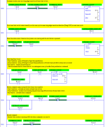
For example, consider a simple hydraulic system that needs to extend to an outer limit switch, then retract to an inner limit switch. There is also a start/stop button. This would take all of three rungs:
Untitled2.png


==================================================
Adding an integer stroke count to limit the number of strokes, somewhat analogous to your steps, requires but a few more rungs:
Untitled.png
 

Similar Topics

Hello everyone, I'm having issues with connected components. I got a new laptop and I installed all the RA programs I need without problem. I was...
Replies
1
Views
309
was trying to use Connected Components to connect to a 525 drive via usb with the face off but can't seem to connect to it. the screen lights up...
Replies
7
Views
794
So I'm using CCW to program a panel view and this is not my first I have done many. My Problem is I get an error message that I have never seen...
Replies
2
Views
500
How do you expand a branch in connected components workbench. Example i want to add an interlock around more than one contact. Most software you...
Replies
14
Views
1,285
I’m working on a conveyor project for work. We’re trying to install a few diverts to carry product directly to one of two trailer doors. I have...
Replies
5
Views
1,060
Back
Top Bottom